10.
MCM2082201-01
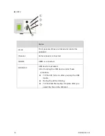
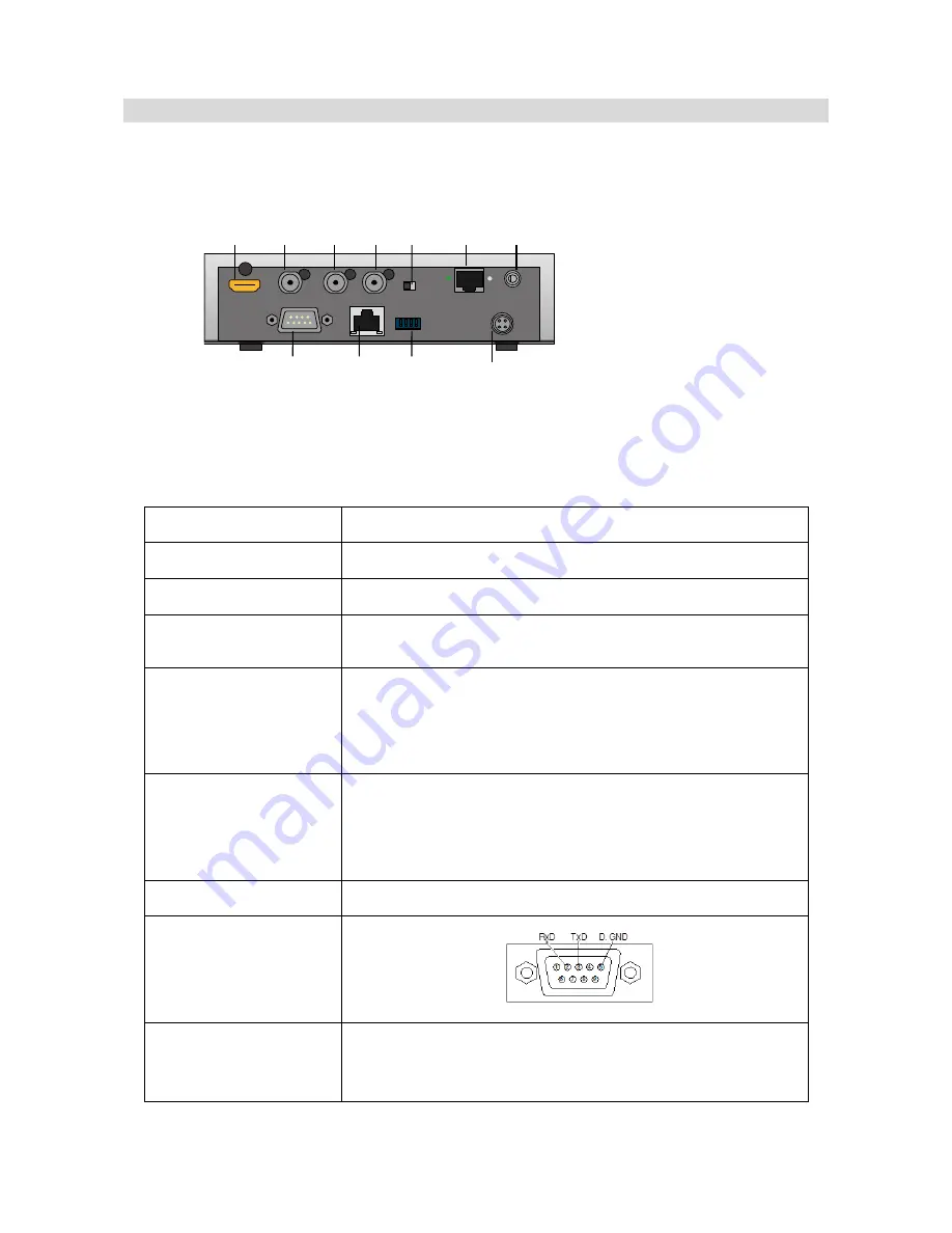
3.2 CCU Rear Panel
● Rear Panel
①HDMI
HDMI output terminal
②HD-SDI OUT
HD-SDI(HD)output terminal
③VIDEO OUT
Composite video(SD)output terminal
④GENLOCK
Gen Lock input terminal.
Input Black Burst, Bi-Level Sync signal.
⑤TERM. ON
75Ω terminator switch.
Left: Turn the terminator on when the Genlock signal
connect to the other device on the loop.
Right: When this device is the last on the loop.
⑥CAMERA
Camera connection port.
• The camera connection port of the CCU is the same shape
as LAN port. Make sure not to connect the PC to the camera
connection port.
⑦Ext. (IR-receiver)
Receiving infrared rays from the remote controller (optional).
⑧RS-232C
RS-232C connection terminal.
⑨LAN
LAN connection terminal (RJ-45, 100BASE-TX/10BASE-T)
supporting 100Base-TX/10Base-T Auto-Negotiation. Use
the Cat5 (or above) Ethernet cable.
① ② ③ ④ ⑤ ⑥ ⑦
⑩
⑧
⑨
⑪
<
RS-232C pin assignment
>


