264
ARRANGEMENT FOR THE OPERATION OF OPTIONAL EQUIPMENT WITH UNIDIRECTIONAL OIL FLOW
6.8 ARRANGEMENT FOR THE OPERATION OF OPTIONAL
EQUIPMENT WITH UNIDIRECTIONAL OIL FLOW
6.8.1 DESCRIPTION AND CONTROL
6.8.1.1
VERSION WITH STANDARD CONTROLS
6.8.1.2
VERSION WITH SERVO CONTROLS
(if installed)
DANGER
•
Some equipment that can be installed instead of the standard bucket make the machine unsuitable for
travelling on roads. Before travelling on roads, always make sure that the machine is homologated for
travelling with the equipment with which it is provided.
•
The installation and removal of the equipment that is not homologated for travelling on roads must be
carried out at the work site or in any case in delimited spaces with no traffic.
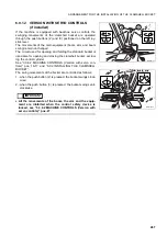
The machine can be equipped with an independent hydraulic cir-
cuit to be used for the operation of optional equipment that may
be installed on the backhoe instead of the standard bucket.
RWA35100
RIGHT SIDE
PRESSURE
LEFT SIDE
PRESSURE
1
2
RWA38150
3
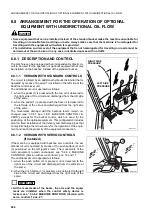
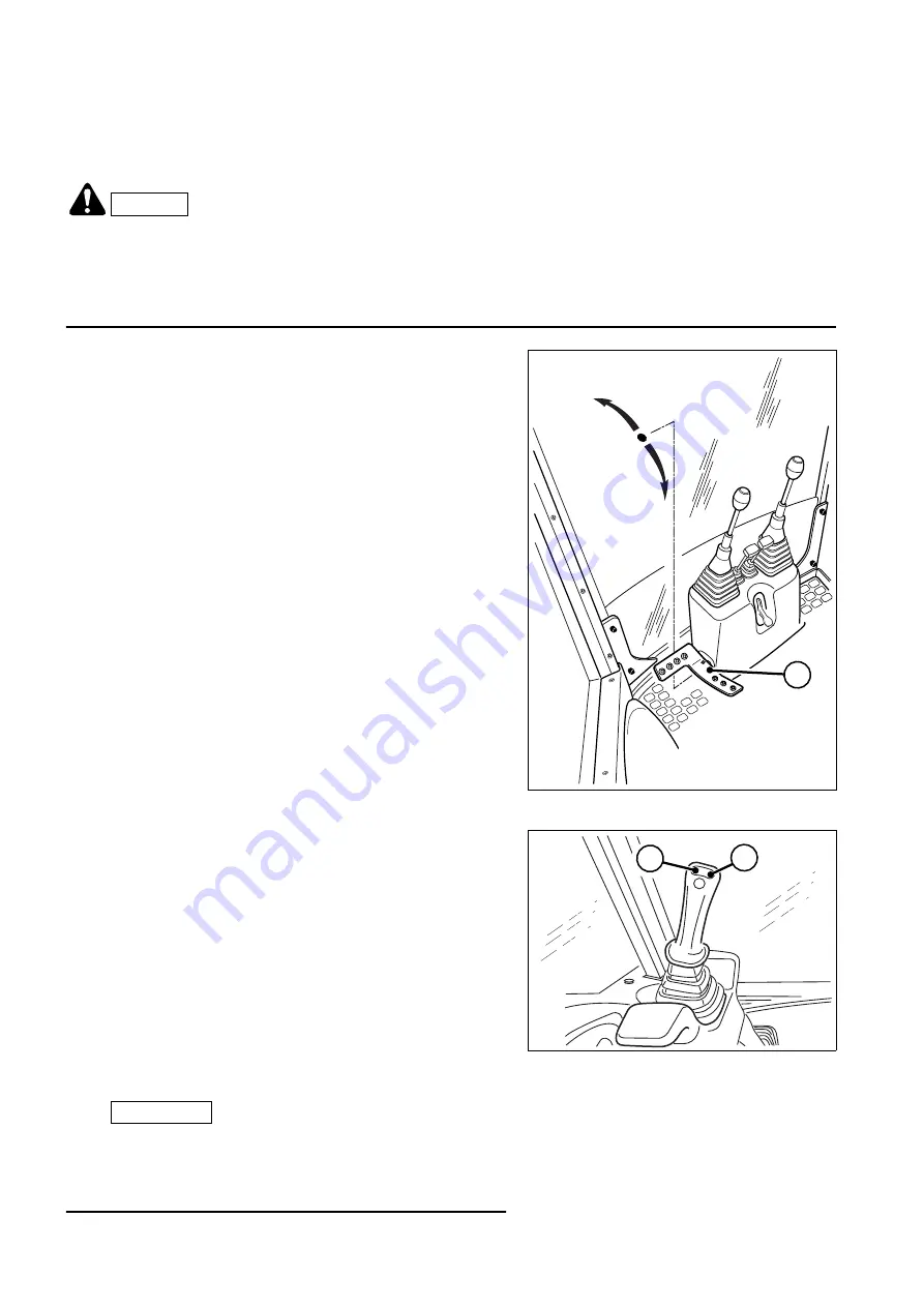
The circuit is piloted by an additional hydraulic distributor that is
operated by means of a pedal (1) installed on the left side of the
backhoe control lever unit.
The additional circuit is operated as follows:
1 - when the pedal (1) is pressed with the toe, oil is delivered to
the right side of the circuit and discharged from the left side
of the same;
2 - when the pedal (1) is pressed with the heel, oil is delivered to
the left side of the circuit and discharged from the right side
of the same.
The movements obtained with the backhoe levers remain un-
changed (see “3.3.6.1 pos. 16-17 BACKHOE CONTROL LE-
VERS”), except for the bucket control, which is used for the
positioning of the optional equipment. This configuration includes
also the fixed installation of the delivery and discharge pipes that
convey/discharge the oil necessary for the operation of the equip-
ment and reach the proximity of the equipment connection.
If the machine is equipped with backhoe servo controls, the ad-
ditional circuit is operated by means of the push buttons (2) and
(3) positioned on the left joystick lever. The movements of the
main equipment remain unchanged, see “3.3.6.2 MACHINE
CONTROLS (Version with servo controls)” pos. 16 and 17.
The additional circuit is operated as follows:
1 - when the push button (2) is pressed, oil is delivered to the
right side of the circuit and discharged from the left side of
the same;
2 - when the push button (3) is pressed, oil is delivered to the left
side of the circuit and discharged from the right side of the
same.
IMPORTANT
☞
•
All the movements of the boom, the arm and the equip-
ment are inhibited when the control safety device is
locked, see “3.3.6.2 MACHINE CONTROLS (Version with
servo controls)” pos. 27.
Summary of Contents for Avance WB91R-2
Page 2: ......
Page 12: ...10 THIS PAGE WAS INTENTIONALLY LEFT EMPTY ...
Page 21: ...SAFETY AND ACCIDENT PREVENTION ...
Page 56: ...54 THIS PAGE WAS INTENTIONALLY LEFT EMPTY ...
Page 57: ...THE MACHINE AND ITS OPERATIONS ...
Page 124: ...122 THIS PAGE WAS INTENTIONALLY LEFT EMPTY ...
Page 159: ...MAINTENANCE ...
Page 229: ...TECHNICAL SPECIFICATIONS ...
Page 238: ...236 THIS PAGE WAS INTENTIONALLY LEFT EMPTY ...
Page 239: ...AUTHORISED OPTIONAL EQUIPMENT ...

