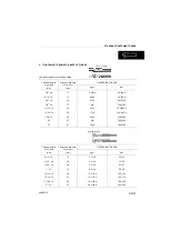
WB97S-5
00-9
HOISTING INSTRUCTIONS
HOISTING INSTRUCTIONS
4
1. If a part cannot be smoothly removed from the ma-
chine by hoisting, the following checks should be
made:
•
Check for removal of all bolts fastening the part to
the relative parts.
•
Check for any part causing interference with the
part to be removed.
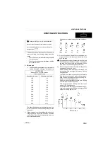
2. Wire ropes
1) Use adequate ropes depending on the weight of
parts to be hoisted, referring to the table below:
The allowable load value is estimated to be one-
sixth or one-seventh of the breaking strength of the
rope used.
2) Sling wire ropes from the middle portion of the hook.
Slinging near the edge of the hook may cause the
rope to slip off the hook during hoisting, and a se-
rious accident can result.
Hooks have maximum strength at the middle por-
tion.
3) Do not sling a heavy load with one rope alone, but
sling with two or more ropes symmetrically wound
on to the load.
k
Slinging with one rope may cause turning of the load
during hoisting, untwisting of the rope, or slipping of
the rope from its original winding position on the
load, which can cause dangerous accidents.
4) Do not sling a heavy load with ropes forming a wide
hanging angle from the hook.
When hoisting a load with two or more ropes, the
force subjected to each rope will increase with the
hanging angles.
The table below shows the variation of allowable
load (kg) when hoisting is made with two ropes,
each of which is allowed to sling up to 1000 kg ver-
tically, at various handing angles.
When two ropes sling a load vertically, up to 2000 kg
of total weight can be suspended.
This weight becomes 1000 kg when two ropes
make a 120° hanging angle.
On the other hand, two ropes are subjected to an ex-
cessive force as large as 4000 kg if they sling a 2000
kg load at a lifting angle of 150°.
k
Heavy parts (25 kg or more) must be lifted with a
hoist etc. In the Disassembly and Assembly section,
every part weighing 25 kg or more is clearly indicated
with the symbol
4
WIRE ROPES
(Standard «S» or «Z» twist ropes
without galvanizing)
Rope diameter (mm)
Allowable load (tons)
10.0
11.2
12.5
14.0
16.0
18.0
20.0
22.4
30.0
40.0
50.0
60.0
1.0
1.4
1.6
2.2
2.8
3.6
4.4
5.6
10.0
18.0
28.0
40.0
Summary of Contents for WB97S-5
Page 1: ...WEBM007500 WB97S 5 BACKHOE LOADER SERIAL NUMBER F00003 and up WB97S 5 SHOP MANUAL ...
Page 2: ......
Page 4: ...PAGE INTENTIONALLY LEFT BLANK ...
Page 48: ...PAGE INTENTIONALLY LEFT BLANK ...
Page 50: ...PAGE INTENTIONALLY LEFT BLANK ...
Page 65: ...PAGE INTENTIONALLY LEFT BLANK ...
Page 144: ...PAGE INTENTIONALLY LEFT BLANK ...
Page 146: ......
Page 161: ...TESTING AND ADJUSTMENTS WB97S 5 20 17 NORMAL OR STANDARD TECHNICAL DATA Fig S RKZ10830 ...
Page 264: ...PAGE INTENTIONALLY LEFT BLANK ...
Page 400: ...PAGE INTENTIONALLY LEFT BLANK ...
Page 508: ...PAGE INTENTIONALLY LEFT BLANK ...
Page 566: ......
Page 581: ...40 15 WB97S 5 STANDARD MAINTENANCE CONTROL VALVE RKZ09071 C C B B A A AE AE X View X ...
Page 589: ...40 23 WB97S 5 STANDARD MAINTENANCE CONTROL VALVE ViewX RKZ09591 C C B B A A AE AE ...
Page 603: ...PAGE INTENTIONALLY LEFT BLANK ...
Page 610: ......
Page 611: ...90 1 WB97S 5 90 OTHER ELECTRICAL DIAGRAM STANDARD VERSION 3 ...
Page 612: ......
Page 614: ......
Page 615: ......
Page 616: ... 2006 KOMATSU UTILITY EUROPE S p A All Rights Reserved Printed in Europe 06 2006 ...


