USING THE WORK EQUIPMENT
136
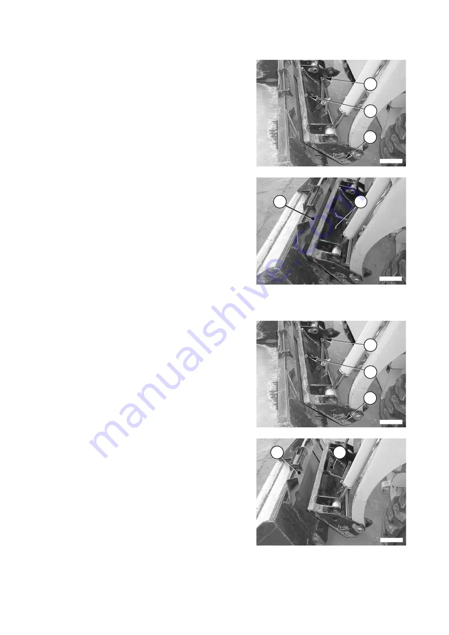
3.13.6.1 RELEASING THE BUCKET
1 - Lower the arm completely and rest the bucket on to the
ground in horizontal position.
2 - Stop the engine, release the residual pressures and lock
the safety bars.
3 - Rotate the lever (1) to the left to release the coupling pins
(2).
4 - Start the machine again and move gradually in reverse, at
the same time rotating the tool-holder plate (3) completely
forward until releasing it from the upper seat on the bucket
(4).
3.13.6.2 COUPLING THE BUCKET
1 - Make sure that the lever (1) is rotated completely to the
left and that the coupling pins (2) have moved completely
backward.
2 - Incline the tool-holder (3) forward and gradually approach
the bucket (4) until centering its upper lip with the edge of
the tool-holder cross member.
2
RWAA11870
2
1
3
RWAA11880
4
2
RWAA11870
2
1
4
RWAA11890
3
Summary of Contents for 37BF50111
Page 2: ......
Page 17: ...SAFETY AND ACCIDENT PREVENTION 15...
Page 19: ...SAFETY NOISE AND VIBRATION PLATES 17 RWA00010 RWA37020...
Page 21: ...SAFETY NOISE AND VIBRATION PLATES 19 RWA37040 RWA00010 RWA00020...
Page 53: ...THE MACHINE AND ITS OPERATIONS 51...
Page 62: ...GENERAL VIEWS 60 10 Left console switches 11 Right console switches RWAA9720 11 RWAA11260 10...
Page 154: ...152 PAGE INTENTIONALLY LEFT BLANK...
Page 155: ...MAINTENANCE 153...
Page 205: ...TECHNICAL SPECIFICATIONS 203...
Page 213: ...TECHNICAL DATA 211 SOLID TYRES SIZE MAKE 10x16 5 AIR BOSS...
Page 214: ...212 PAGE INTENTIONALLY LEFT BLANK...
Page 215: ...AUTHORISED OPTIONAL EQUIPMENT 213...
Page 242: ...240 PAGE INTENTIONALLY LEFT BLANK...
Page 243: ......
Page 244: ...2004 KOMATSU UTILITY EUROPE S p A All Rights Reserved Printed in Europe...


