MAINTENANCE PROCEDURE
173
4.8 MAINTENANCE PROCEDURE
4.8.1 WHEN REQUIRED
4.8.1.a
CHECKING, CLEANING OR CHANGING
THE AIR CLEANER CARTRIDGE
WARNING
q
Remove the air cleaner only after stopping the engine
and do not start the engine if the air cleaner is open.
q
Always wear goggles while cleaning the filter.
IMPORTANT
q
The air filtering system comprises a primary filtering
element with great capacity and a secondary cartridge
that provides additional safety protection.
The primary element can be cleaned with compressed
air, while the safety cartridge must only be changed.
q
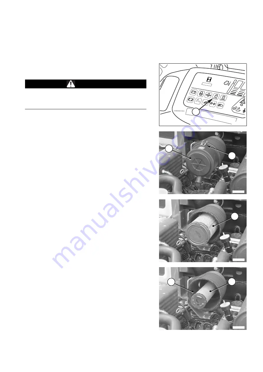
The filtering element must be cleaned when the clog-
ging warning light (A) positioned on the instrument pa-
nel blinks or comes on completely.
In any case, check whether the cartridge is clogged eve-
ry 50 hours of operation.
q
The filtering element must be cleaned even when the
need for cleaning is signalled by the clogging indicator.
The air cleaner can be reached after lifting the engine hood
(see "3.5.1 ENGINE HOOD") and opening the rear panel (see
"3.5.2 REAR PANEL").
To clean the primary element, proceed as follows:
1 - Remove the couplings (1) and remove the clogging filter
cover (2).
2 - Extract the main filtering element (3).
3 - Slightly strike the element on the palm of your hand to eli-
minate the dust and blow compressed air on the inner sur-
face, keeping the air jet at a distance of approximately 15
cm and making sure that the pressure does not exceed 4-
5 bars.
4 - Carefully clean the filter casing (4), taking care to avoid
the introduction of foreign matters in the suction duct and
reassemble the unit making sure that the ejector is posi-
tioned vertically and at the bottom.
IMPORTANT
q
If the clogging warning light comes on after the engine
has started, it is necessary to change the primary filter-
ing element and the safety cartridge.
q
Change the primary filtering element after 5 cleaning op-
erations or after one year.
The safety cartridge must always be changed together
with the primary filtering element.
H
C
P
RWA32410
A
2
RKAB1550
1
3
RKAB1560
5
RKAB1570
4
Summary of Contents for 37BF50111
Page 2: ......
Page 17: ...SAFETY AND ACCIDENT PREVENTION 15...
Page 19: ...SAFETY NOISE AND VIBRATION PLATES 17 RWA00010 RWA37020...
Page 21: ...SAFETY NOISE AND VIBRATION PLATES 19 RWA37040 RWA00010 RWA00020...
Page 53: ...THE MACHINE AND ITS OPERATIONS 51...
Page 62: ...GENERAL VIEWS 60 10 Left console switches 11 Right console switches RWAA9720 11 RWAA11260 10...
Page 154: ...152 PAGE INTENTIONALLY LEFT BLANK...
Page 155: ...MAINTENANCE 153...
Page 205: ...TECHNICAL SPECIFICATIONS 203...
Page 213: ...TECHNICAL DATA 211 SOLID TYRES SIZE MAKE 10x16 5 AIR BOSS...
Page 214: ...212 PAGE INTENTIONALLY LEFT BLANK...
Page 215: ...AUTHORISED OPTIONAL EQUIPMENT 213...
Page 242: ...240 PAGE INTENTIONALLY LEFT BLANK...
Page 243: ......
Page 244: ...2004 KOMATSU UTILITY EUROPE S p A All Rights Reserved Printed in Europe...


