MAINTENANCE PROCEDURE
176
4.8.1.d
RELEASING THE PARKING BRAKE
WARNING
q
In case of failure of the hydraulic system and before re-
moving the machine, release the negative brake in-
stalled on the travel motors.
The release of the parking brake is obtained by acting on the
negative brake installed on the travel motors, according to the
following procedure.
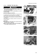
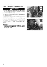
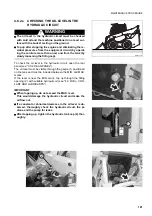
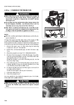
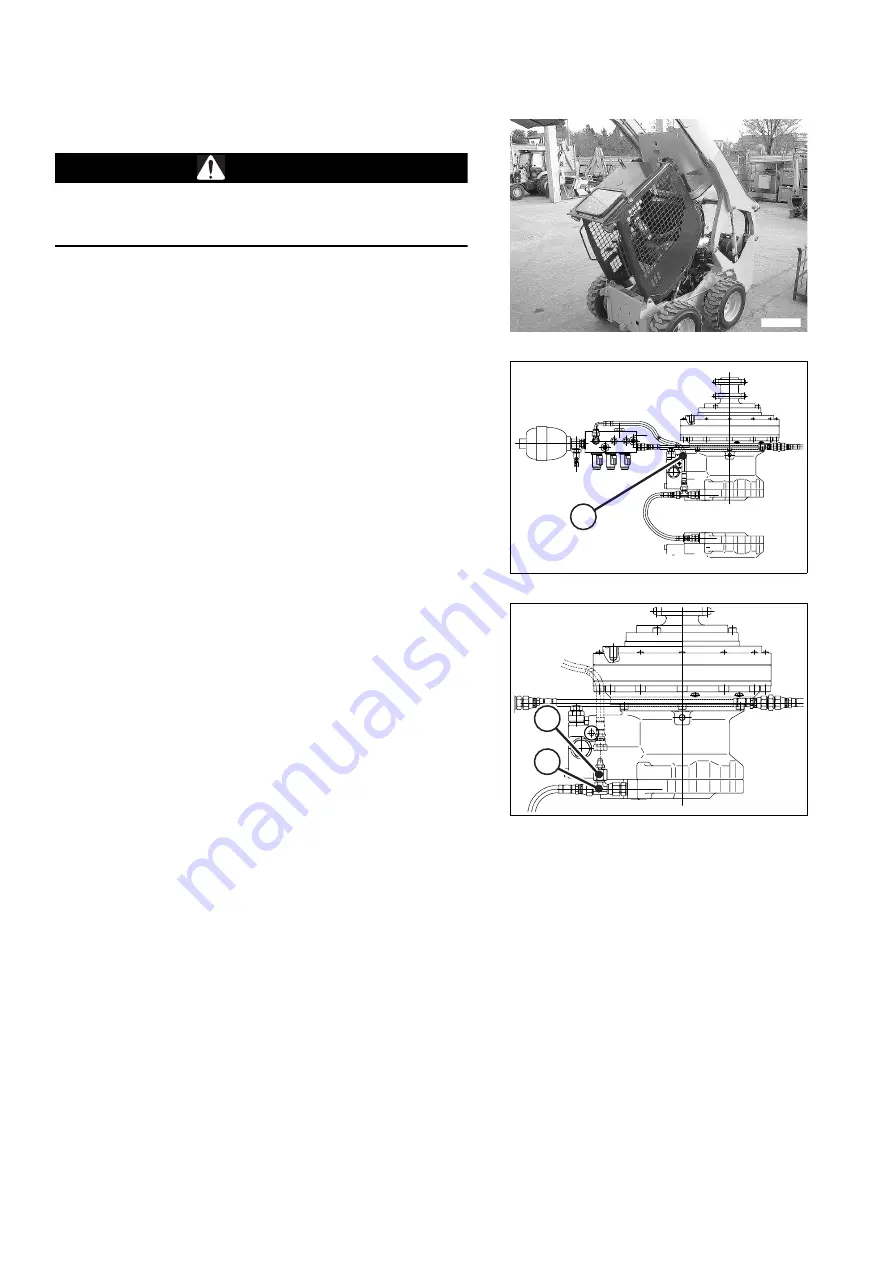
1 - Raise the cab (see "3.5.3.1 RAISING THE CAB").
2 - Disconnect the pipe (1) that supplies pressure to the tra-
vel motors.
3 - Connect the grease nipple (3) to the union (2).
4 - Using the grease pump provided, inject grease until rea-
ching the minimum pressure required to release the
brake.
5 - After releasing the brake, carry out the necessary mainte-
nance operations.
6 - To restore the braking circuit to the standard configura-
tion, remove the grease nipple (3) from the coupling (2)
and put back the pipe (1).
7 - Lower the cab (see "3.5.3.1 RAISING THE CAB").
NOTE
q
After restoring the circuit to the standard configuration, it is
not necessary to carry out any adjustment.
RWAB0030
RWA36030
1
RWA36040
3
2
Summary of Contents for 37BF50111
Page 2: ......
Page 17: ...SAFETY AND ACCIDENT PREVENTION 15...
Page 19: ...SAFETY NOISE AND VIBRATION PLATES 17 RWA00010 RWA37020...
Page 21: ...SAFETY NOISE AND VIBRATION PLATES 19 RWA37040 RWA00010 RWA00020...
Page 53: ...THE MACHINE AND ITS OPERATIONS 51...
Page 62: ...GENERAL VIEWS 60 10 Left console switches 11 Right console switches RWAA9720 11 RWAA11260 10...
Page 154: ...152 PAGE INTENTIONALLY LEFT BLANK...
Page 155: ...MAINTENANCE 153...
Page 205: ...TECHNICAL SPECIFICATIONS 203...
Page 213: ...TECHNICAL DATA 211 SOLID TYRES SIZE MAKE 10x16 5 AIR BOSS...
Page 214: ...212 PAGE INTENTIONALLY LEFT BLANK...
Page 215: ...AUTHORISED OPTIONAL EQUIPMENT 213...
Page 242: ...240 PAGE INTENTIONALLY LEFT BLANK...
Page 243: ......
Page 244: ...2004 KOMATSU UTILITY EUROPE S p A All Rights Reserved Printed in Europe...


