MAINTENANCE PROCEDURE
189
4.8.6.f
LUBRICATING THE JOINTS
IMPORTANT
q
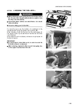
Clean the grease nipples before applying the greasing pump.
q
After lubrication, remove any excess grease.
q
If the machine is used in difficult conditions, perform these maintenance operations more frequently.
These maintenance operations must be carried out with the arm completely lowered and the bucket resting on the
ground. For the lubrication, use a syringe and the recommended grease.
(See "4.3 FUEL, COOLANT AND LUBRICANTS").
NOTE
q
As a general rule, consider that each cylinder is provided with two grease nipples positioned on the couplings
and that each pin serving as fulcrum for a movement is provided with at least one grease nipple.
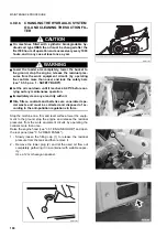
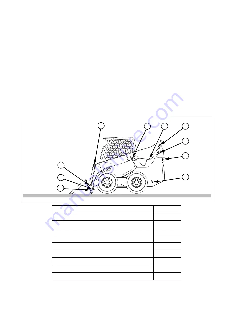
EQUIPMENT LUBRICATION POINTS
1 - Bucket coupling pin
(2 points)
2 - Tool-holder plate fulcrum pin
(2 points)
3 - Bucket cylinder head pin
(2 points)
4 - Bucket cylinder base pin
(2 points)
5 - Frame front lever pin
(2 points)
6 - Arm front lever pin
(2 points)
7 - Arm rear lever pin
(2 points)
8 - Lifting cylinder head pin
(2 points)
9 - Frame rear lever pin
(2 points)
10 - Lifting cylinder base pin
(2 points)
RWA37610
1
2
3
4
5
6
7
8
9
10
Summary of Contents for 37BF50111
Page 2: ......
Page 17: ...SAFETY AND ACCIDENT PREVENTION 15...
Page 19: ...SAFETY NOISE AND VIBRATION PLATES 17 RWA00010 RWA37020...
Page 21: ...SAFETY NOISE AND VIBRATION PLATES 19 RWA37040 RWA00010 RWA00020...
Page 53: ...THE MACHINE AND ITS OPERATIONS 51...
Page 62: ...GENERAL VIEWS 60 10 Left console switches 11 Right console switches RWAA9720 11 RWAA11260 10...
Page 154: ...152 PAGE INTENTIONALLY LEFT BLANK...
Page 155: ...MAINTENANCE 153...
Page 205: ...TECHNICAL SPECIFICATIONS 203...
Page 213: ...TECHNICAL DATA 211 SOLID TYRES SIZE MAKE 10x16 5 AIR BOSS...
Page 214: ...212 PAGE INTENTIONALLY LEFT BLANK...
Page 215: ...AUTHORISED OPTIONAL EQUIPMENT 213...
Page 242: ...240 PAGE INTENTIONALLY LEFT BLANK...
Page 243: ......
Page 244: ...2004 KOMATSU UTILITY EUROPE S p A All Rights Reserved Printed in Europe...


