MAINTENANCE PROCEDURE
196
4.8.8.d
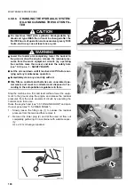
DRAINING THE HYDRAULIC OIL TANK
(Only for machines filled with synthetic
biodegradable oil type HEES)
WARNING
q
Lower the loader arm completely, rest the bucket on to
the ground and, after stopping the engine, eliminate the
residual pressures that may be present in the equip-
ment (by operating the controls more than once) and
lock the safety bars (see "3.3.5 pos. 1 - SAFETY
BARS").
q
Let the oil cool down until it reaches 40-45ºC before per-
forming any maintenance operation.
q
Immediately clean any area dirty with oil.
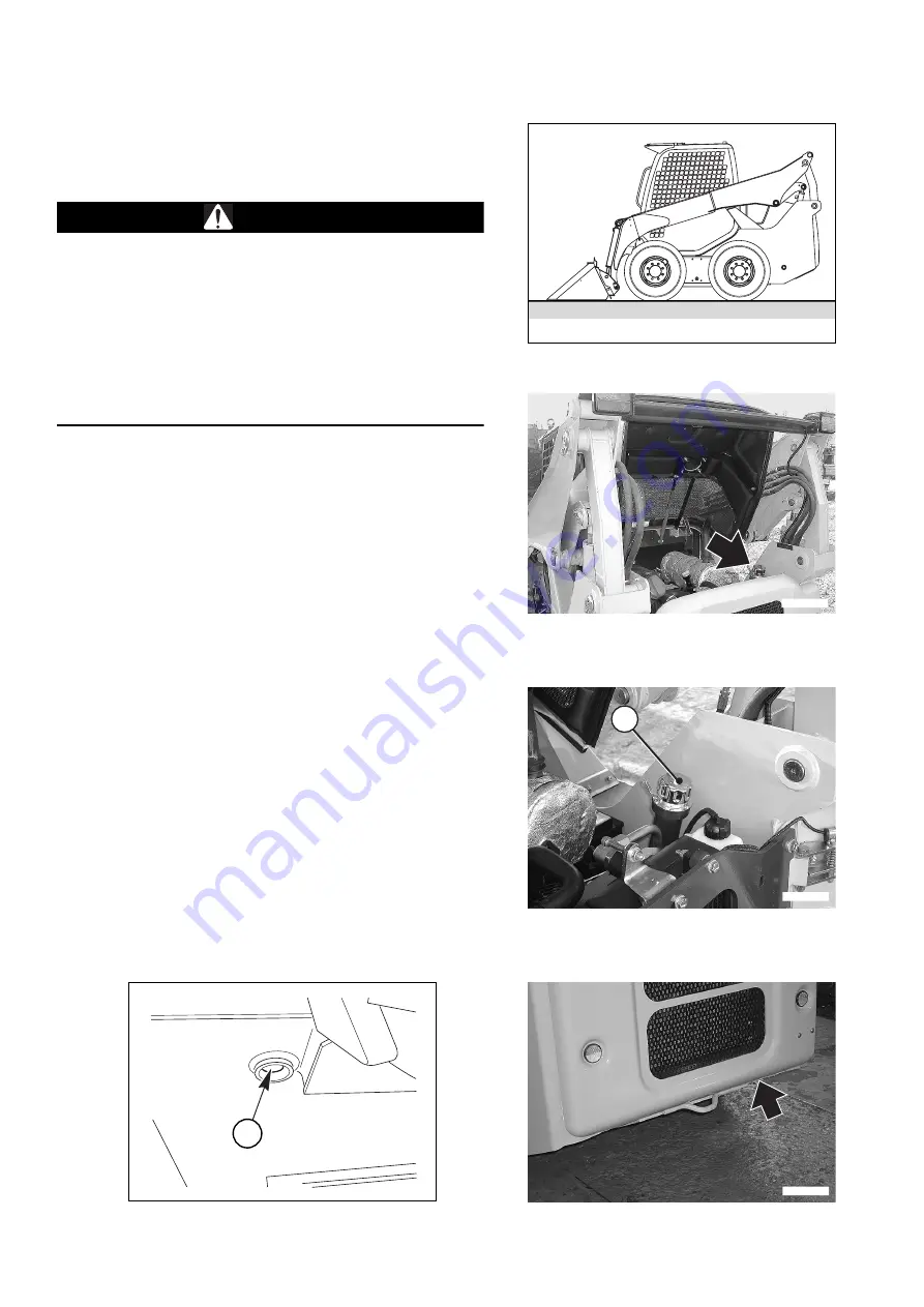
Stop the machine on a firm and level surface, lower the equip-
ment to the ground, stop the engine and release the residual
pressures that may be present in the equipment by operating
the controls more than once.
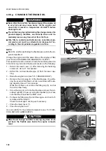
Raise the engine hood (see "3.5.1 ENGINE HOOD") and open
the rear panel (see "3.5.2 REAR PANEL").
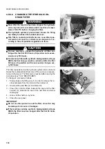
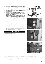
1 - Slowly loosen the filling cap (1) to release the residual
pressure from the tank and remove it.
2 - Loosen the lower plug (2) until the condensate has flown
out of the tank completely.
Use a 12 mm hexagon spanner.
3 - Put back the lower plug (2), the filling cap (1) and close
the rear panel and the engine hood.
IMPORTANT
q
The draining of the tank must be carried out at tempera-
tures exceeding 0ºC, before starting the engine; when
the temperature is below 0ºC, the hydraulic oil tank must
be drained at the end of work, or in any case when the
temperature of the machine is sufficiently high to pre-
vent the condensate from freezing and to allow it to flow
out of the tank without problems.
RWA37070
RWAA13460
1
RWAA13410
RWAA10390
RWA34230
2
Summary of Contents for 37BF50111
Page 2: ......
Page 17: ...SAFETY AND ACCIDENT PREVENTION 15...
Page 19: ...SAFETY NOISE AND VIBRATION PLATES 17 RWA00010 RWA37020...
Page 21: ...SAFETY NOISE AND VIBRATION PLATES 19 RWA37040 RWA00010 RWA00020...
Page 53: ...THE MACHINE AND ITS OPERATIONS 51...
Page 62: ...GENERAL VIEWS 60 10 Left console switches 11 Right console switches RWAA9720 11 RWAA11260 10...
Page 154: ...152 PAGE INTENTIONALLY LEFT BLANK...
Page 155: ...MAINTENANCE 153...
Page 205: ...TECHNICAL SPECIFICATIONS 203...
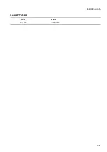
Page 213: ...TECHNICAL DATA 211 SOLID TYRES SIZE MAKE 10x16 5 AIR BOSS...
Page 214: ...212 PAGE INTENTIONALLY LEFT BLANK...
Page 215: ...AUTHORISED OPTIONAL EQUIPMENT 213...
Page 242: ...240 PAGE INTENTIONALLY LEFT BLANK...
Page 243: ......
Page 244: ...2004 KOMATSU UTILITY EUROPE S p A All Rights Reserved Printed in Europe...


