USING THE WORK EQUIPMENT
141
3.13.7.3 CHECKING THE POSITION OF THE
LOCKING PINS
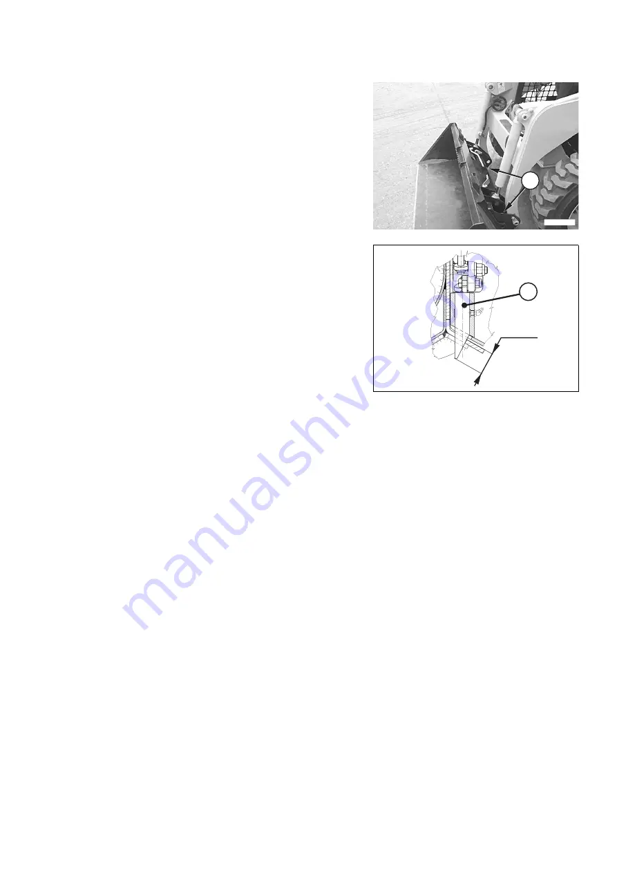
The position of the pins (1) must be checked with the levers in
locked or horizontal position. The length of the protruding part
of the pins must be in compliance with the prescribed values,
as indicated in the figure.
To check the length of the protruding part of the pins, proceed
as follows:
1 - Slowly raise the arm.
2 - Rotate the bucket or the equipment forward, until the pro-
truding part of the pins can be seen by the operator with
no need to leave his seat.
3 - If the length (1) is not within the specified range of values,
adjust it by proceeding as indicated in paragraph "3.13.7.4
ADJUSTING THE LOCKING PINS".
RWAA12520
1
RWA36370
1
43±2
Summary of Contents for 37BF50111
Page 2: ......
Page 17: ...SAFETY AND ACCIDENT PREVENTION 15...
Page 19: ...SAFETY NOISE AND VIBRATION PLATES 17 RWA00010 RWA37020...
Page 21: ...SAFETY NOISE AND VIBRATION PLATES 19 RWA37040 RWA00010 RWA00020...
Page 53: ...THE MACHINE AND ITS OPERATIONS 51...
Page 62: ...GENERAL VIEWS 60 10 Left console switches 11 Right console switches RWAA9720 11 RWAA11260 10...
Page 154: ...152 PAGE INTENTIONALLY LEFT BLANK...
Page 155: ...MAINTENANCE 153...
Page 205: ...TECHNICAL SPECIFICATIONS 203...
Page 213: ...TECHNICAL DATA 211 SOLID TYRES SIZE MAKE 10x16 5 AIR BOSS...
Page 214: ...212 PAGE INTENTIONALLY LEFT BLANK...
Page 215: ...AUTHORISED OPTIONAL EQUIPMENT 213...
Page 242: ...240 PAGE INTENTIONALLY LEFT BLANK...
Page 243: ......
Page 244: ...2004 KOMATSU UTILITY EUROPE S p A All Rights Reserved Printed in Europe...


