USING THE WORK EQUIPMENT
142
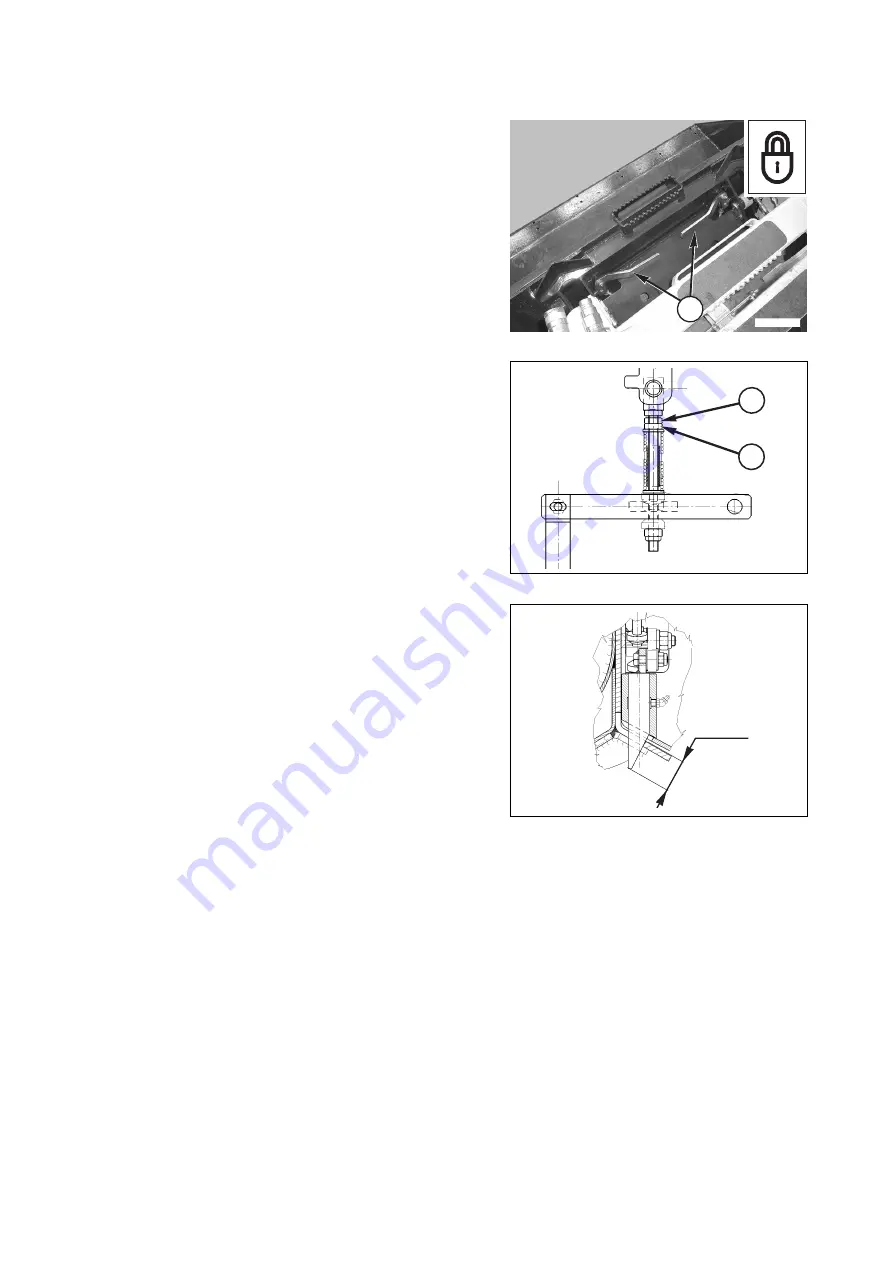
3.13.7.4 ADJUSTING THE LOCKING PINS
The pins must be adjusted with the bucket resting flat on the
ground and the levers (1) of the rapid coupling in horizontal or
locking position, proceeding as indicated below:
1 - Check the protrusion of the locking pins, proceeding as in-
dicated in paragraph "3.13.7.3 CHECKING THE POSI-
TION OF THE LOCKING PINS".
2 - Loosen the lock nut (3).
3 - Adjust the nut (2) until reaching the prescribed value.
4 - Tighten the lock nut (3) until it makes contact with the
adjusting nut (2), in order to maintain the specified length.
RWA36390
43±2
RWA36380
2
3
1
RWAA12540
Summary of Contents for 37BF50111
Page 2: ......
Page 17: ...SAFETY AND ACCIDENT PREVENTION 15...
Page 19: ...SAFETY NOISE AND VIBRATION PLATES 17 RWA00010 RWA37020...
Page 21: ...SAFETY NOISE AND VIBRATION PLATES 19 RWA37040 RWA00010 RWA00020...
Page 53: ...THE MACHINE AND ITS OPERATIONS 51...
Page 62: ...GENERAL VIEWS 60 10 Left console switches 11 Right console switches RWAA9720 11 RWAA11260 10...
Page 154: ...152 PAGE INTENTIONALLY LEFT BLANK...
Page 155: ...MAINTENANCE 153...
Page 205: ...TECHNICAL SPECIFICATIONS 203...
Page 213: ...TECHNICAL DATA 211 SOLID TYRES SIZE MAKE 10x16 5 AIR BOSS...
Page 214: ...212 PAGE INTENTIONALLY LEFT BLANK...
Page 215: ...AUTHORISED OPTIONAL EQUIPMENT 213...
Page 242: ...240 PAGE INTENTIONALLY LEFT BLANK...
Page 243: ......
Page 244: ...2004 KOMATSU UTILITY EUROPE S p A All Rights Reserved Printed in Europe...


