INSTRUMENTS AND CONTROLS
92
10 - SPEED INCREASE CONTROL
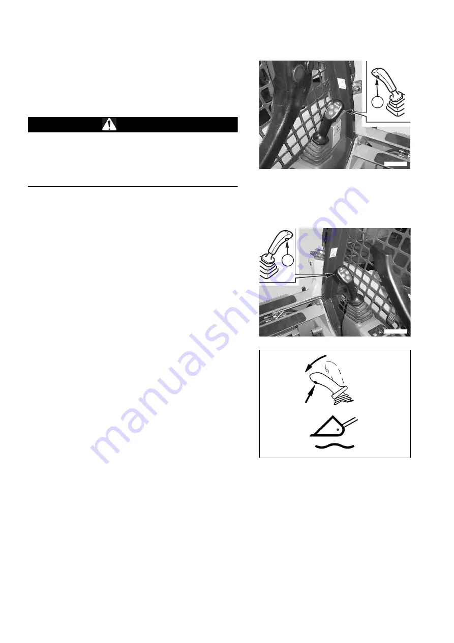
The button (1) that allows the machine travel speed to be in-
creased is positioned on the left joystick grip.
When the button is pressed, the speed increases; release the
button to return to normal speed.
CAUTION
q
The speed increase function should be used only for the
fast speed transfers of the machine; in any other case, it
is advisable to use the normal speed.
q
Do not use the speed increase control when performing
steering or counterrotation manoeuvres.
11 - FLOATING DEVICE CONTROL
(IF INSTALLED)
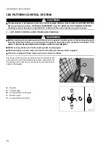
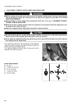
The right joystick grip is provided with a switch (1) that when
pressed (WARNING LIGHT ON) (see "3.3.2 pos. 8 - FLOA-
TING DEVICE WARNING LIGHT"), frees the loader arm (float-
ing position), that is, allows it to automatically follow the
undulations of the ground.
Press the switch again to restore the standard operating con-
ditions (WARNING LIGHT OFF) ("3.3.2 pos. 8 - FLOATING
DEVICE WARNING LIGHT").
RWAA11320
1
RWAA11330
1
RWA35990
Summary of Contents for 37BF50111
Page 2: ......
Page 17: ...SAFETY AND ACCIDENT PREVENTION 15...
Page 19: ...SAFETY NOISE AND VIBRATION PLATES 17 RWA00010 RWA37020...
Page 21: ...SAFETY NOISE AND VIBRATION PLATES 19 RWA37040 RWA00010 RWA00020...
Page 53: ...THE MACHINE AND ITS OPERATIONS 51...
Page 62: ...GENERAL VIEWS 60 10 Left console switches 11 Right console switches RWAA9720 11 RWAA11260 10...
Page 154: ...152 PAGE INTENTIONALLY LEFT BLANK...
Page 155: ...MAINTENANCE 153...
Page 205: ...TECHNICAL SPECIFICATIONS 203...
Page 213: ...TECHNICAL DATA 211 SOLID TYRES SIZE MAKE 10x16 5 AIR BOSS...
Page 214: ...212 PAGE INTENTIONALLY LEFT BLANK...
Page 215: ...AUTHORISED OPTIONAL EQUIPMENT 213...
Page 242: ...240 PAGE INTENTIONALLY LEFT BLANK...
Page 243: ......
Page 244: ...2004 KOMATSU UTILITY EUROPE S p A All Rights Reserved Printed in Europe...


