background image

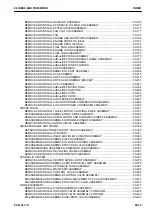
E-47  WHEN  WINDOW  WASHER  SWITCH  IS  OPERATED,  WINDOW  WASHER  DOES  NOT  OPER-

ATE .........................................................................................................................................40-1028

E-48 BOOM RAISE INDICATOR IS NOT DISPLAYED PROPERLY WITH MONITORING FUNCTION ...

................................................................................................................................................40-1029

E-49 BOOM LOWER INDICATOR IS NOT DISPLAYED PROPERLY WITH MONITORING FUNCTION .

................................................................................................................................................40-1030

E-50 ARM OUT INDICATOR IS NOT DISPLAYED PROPERLY WITH MONITORING FUNCTION..........

................................................................................................................................................40-1031

E-51 ARM IN INDICATOR IS NOT DISPLAYED PROPERLY WITH MONITORING FUNCTION 40-1032
E-52 BUCKET DUMP INDICATOR IS NOT DISPLAYED PROPERLY WITH MONITORING FUNCTION

................................................................................................................................................40-1033

E-53 BUCKET CURL INDICATOR IS NOT DISPLAYED PROPERLY WITH MONITORING FUNCTION.

................................................................................................................................................40-1034

E-54 SWING INDICATOR IS NOT DISPLAYED PROPERLY WITH MONITORING FUNCTION.40-1035
E-55 TRAVEL INDICATOR IS NOT DISPLAYED PROPERLY WITH MONITORING FUNCTION40-1036
E-56 SERVICE INDICATOR IS NOT DISPLAYED PROPERLY WITH MONITORING FUNCTION 
..........

................................................................................................................................................40-1037

E-57 ATTACHMENT HYDRAULIC CIRCUIT CANNOT BE CHANGED.......................................40-1039
E-58 KOMTRAX SYSTEM DOES NOT OPERATE NORMALLY 
.................................................40-1040

TROUBLESHOOTING FOR HYDRAULIC AND MECHANICAL SYSTEMS (H MODE) .....................40-1041

INFORMATION MENTIONED IN TROUBLESHOOTING TABLE (H MODE)...............................40-1041
SYSTEM CHART OF HYDRAULIC AND MECHANICAL SYSTEMS 
..........................................40-1042
FAILURE MODE AND CAUSE TABLE
........................................................................................40-1044
H-1 ALL WORK EQUIPMENT, SWING AND TRAVEL DO NOT WORK
......................................40-1056
H-2 ALL WORK EQUIPMENT, SWING AND TRAVEL LACK SPEED AND POWER 
..................40-1057
H-3 FINE CONTROL PERFORMANCE OR RESPONSE IS POOR
............................................40-1060
H-4 UNUSUAL NOISE IS HEARD FROM AROUND HYDRAULIC PUMP 
..................................40-1061
H-5 ENGINE SPEED DROPS LARGELY OR ENGINE STOPS 
..................................................40-1062
H-6 SPEED OR POWER OF BOOM IS LOW 
.............................................................................40-1064
H-7 ARM SPEED OR POWER IS LOW 
......................................................................................40-1068
H-8 BUCKET SPEED OR POWER IS LOW
................................................................................40-1073
H-9 WORK EQUIPMENT DOES NOT MOVE IN SINGLE OPERATION 
.....................................40-1076
H-10 HYDRAULIC DRIFT OF BOOM IS LARGE 
........................................................................40-1077
H-11 HYDRAULIC DRIFT OF ARM IS LARGE 
...........................................................................40-1079
H-12 HYDRAULIC DRIFT OF BUCKET IS LARGE
.....................................................................40-1081
H-13 WHEN SINGLE WORK EQUIPMENT IS RELIEVED HYDRAULICALLY, OTHER WORK EQUIP-

MENT MOVES ........................................................................................................................40-1082

H-14 TIME LAG OF WORK EQUIPMENT IS LARGE .................................................................40-1083
H-15 ONE-TOUCH POWER MAXIMIZING FUNCTION DOES NOT OPERATE 
.........................40-1084
H-16 ATTACHMENT CIRCUIT CANNOT BE CHANGED
............................................................40-1085
H-17 OIL FLOW IN ATTACHMENT CIRCUIT CANNOT BE CHANGED 
.....................................40-1086
H-18  IN  COMBINED  OPERATION  OF  WORK  EQUIPMENT,  EQUIPMENT  HAVING  HEAVIER  LOAD

MOVES SLOWER ...................................................................................................................40-1087

H-19 IN COMBINED OPERATION OF SWING AND TRAVEL, TRAVEL SPEED DROPS LARGELY ......

................................................................................................................................................40-1088

H-20 IN COMBINED OPERATION OF SWING AND BOOM RAISE, BOOM RISING SPEED IS LOW ....

................................................................................................................................................40-1089

H-21 MACHINE DOES NOT TRAVEL STRAIGHT ......................................................................40-1090
H-22 MACHINE IS NOT STEERED WELL OR STEERING POWER IS LOW
.............................40-1092
H-23 TRAVEL SPEED IS LOW ...................................................................................................40-1095
H-24 ONE OF TRACKS DOES NOT RUN 
..................................................................................40-1097
H-25 TRAVEL SPEED DOES NOT CHANGE, OR TRAVEL SPEED IS TOO SLOW OR FAST 
..40-1098
H-26 UPPER STRUCTURE DOES NOT SWING BOTH TO THE RIGHT AND LEFT 
.................40-1099
H-27 SWINGS ONLY IN ONE DIRECTION
.................................................................................40-1100
H-28  SWING  ACCELERATION  OR  SWING  SPEED  IS  LOW  IN  BOTH  DIRECTIONS  (RIGHT  AND

LEFT) ......................................................................................................................................40-1101

H-29  SWING  ACCELERATION  PERFORMANCE  IS  POOR  OR  SWING  SPEED  IS  SLOW  IN  ONLY

ONE DIRECTION ....................................................................................................................40-1102

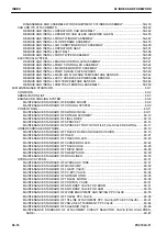
00 INDEX AND FOREWORD

INDEX

PC210LC-11

00-13

Summary of Contents for 500001

Page 1: ...HYDRAULIC EXCAVATOR SEN06516 01 PC210LC 11 SERIAL NUMBERS 500001 and up ...

Page 2: ...Find manuals at https best manuals com ...

Page 3: ...00 INDEX AND FOREWORD PC210LC 11 00 1 Find manuals at https best manuals com ...

Page 4: ...THOD FOR DISCONNECTING AND CONNECTING CONNECTOR WITH LOCK TO PUSH 00 66 METHOD FOR DISCONNECTING AND CONNECTING CONNECTOR WITH HOUSING TO ROTATE 00 68 HOW TO READ ELECTRICAL WIRE CODE 00 69 EXPLANATION OF TERMS FOR MAINTENANCE STANDARD 00 73 STANDARD TIGHTENING TORQUE TABLE 00 76 CONVERSION TABLE 00 83 01 SPECIFICATIONS 01 1 CONTENTS 01 2 ABBREVIATION LIST 01 3 SPECIFICATIONS 01 8 SPECIFICATION DR...

Page 5: ... SWING SYSTEM 10 295 LAYOUT DRAWING OF SWING SYSTEM 10 295 SWING CONTROL SYSTEM DIAGRAM 10 299 COMPONENT PARTS OF SWING SYSTEM 10 303 TRAVEL SYSTEM 10 318 LAYOUT DRAWING OF TRAVEL SYSTEM 10 318 TRAVEL CONTROL SYSTEM DIAGRAM 10 322 COMPONENT PARTS OF TRAVEL SYSTEM 10 324 UNDERCARRIAGE AND FRAME 10 345 LAYOUT DRAWING OF UNDERCARRIAGE 10 345 WORK EQUIPMENT 10 347 STRUCTURE OF WORK EQUIPMENT 10 347 FU...

Page 6: ... TRACK TENSION 30 90 HYDRAULIC SYSTEM 30 92 RELEASE REMAINING PRESSURE FROM HYDRAULIC SYSTEM 30 92 TEST AND ADJUST OIL PRESSURE IN WORK EQUIPMENT SWING AND TRAVEL CIRCUITS 30 93 TEST OIL PRESSURE OF CONTROL CIRCUIT 30 103 TEST AND ADJUST OIL PRESSURE IN PUMP PC CONTROL CIRCUIT 30 105 TEST AND ADJUST OIL PRESSURE IN PUMP LS CONTROL CIRCUIT 30 108 TEST OUTLET PRESSURE OF SOLENOID VALVE 30 115 TEST P...

Page 7: ...FAILURE CODE DISPLAY OF CODE 40 165 FAILURE CODE 879AKA 40 165 FAILURE CODE 879AKB 40 166 FAILURE CODE 879BKA 40 167 FAILURE CODE 879BKB 40 169 FAILURE CODE 879CKA 40 171 FAILURE CODE 879CKB 40 172 FAILURE CODE 879DKZ 40 173 FAILURE CODE 879EMC 40 175 FAILURE CODE 879FMC 40 176 FAILURE CODE 879GKX 40 177 FAILURE CODE 989L00 40 179 FAILURE CODE 989M00 40 180 FAILURE CODE 989N00 40 181 FAILURE CODE ...

Page 8: ...0 265 FAILURE CODE CA352 40 266 FAILURE CODE CA356 40 269 FAILURE CODE CA357 40 271 FAILURE CODE CA386 40 273 FAILURE CODE CA428 40 274 FAILURE CODE CA429 40 276 FAILURE CODE CA435 40 278 FAILURE CODE CA441 40 280 FAILURE CODE CA442 40 282 FAILURE CODE CA449 40 283 FAILURE CODE CA451 40 284 FAILURE CODE CA452 40 286 FAILURE CODE CA488 40 288 FAILURE CODE CA515 40 289 FAILURE CODE CA516 40 291 FAIL...

Page 9: ...0 378 FAILURE CODE CA1993 40 379 FAILURE CODE CA2185 40 382 FAILURE CODE CA2186 40 383 FAILURE CODE CA2249 40 385 FAILURE CODE CA2271 40 386 FAILURE CODE CA2272 40 389 FAILURE CODE CA2288 40 392 FAILURE CODE CA2311 40 393 FAILURE CODE CA2349 40 394 FAILURE CODE CA2353 40 397 FAILURE CODE CA2357 40 399 FAILURE CODE CA2381 40 400 FAILURE CODE CA2382 40 403 FAILURE CODE CA2383 40 406 FAILURE CODE CA2...

Page 10: ...0 511 FAILURE CODE CA3421 40 513 FAILURE CODE CA3497 40 515 FAILURE CODE CA3498 40 516 FAILURE CODE CA3543 40 517 FAILURE CODE CA3545 40 523 FAILURE CODE CA3547 40 525 FAILURE CODE CA3558 40 526 FAILURE CODE CA3559 40 528 FAILURE CODE CA3562 40 530 FAILURE CODE CA3563 40 532 FAILURE CODE CA3567 40 535 FAILURE CODE CA3568 40 538 FAILURE CODE CA3571 40 542 FAILURE CODE CA3572 40 544 FAILURE CODE CA3...

Page 11: ...ILURE CODE CA4169 40 653 FAILURE CODE CA4171 40 655 FAILURE CODE CA4249 40 658 FAILURE CODE CA4251 40 660 FAILURE CODE CA4259 40 662 FAILURE CODE CA4261 40 665 FAILURE CODE CA4277 40 668 FAILURE CODE CA4281 40 671 FAILURE CODE CA4459 40 674 FAILURE CODE CA4461 40 677 FAILURE CODE CA4658 40 680 FAILURE CODE CA4731 40 684 FAILURE CODE CA4732 40 685 FAILURE CODE CA4739 40 686 FAILURE CODE CA4768 40 6...

Page 12: ...ILURE CODE DHPBMA 40 782 FAILURE CODE DHS3MA 40 785 FAILURE CODE DHS4MA 40 788 FAILURE CODE DHS8MA 40 791 FAILURE CODE DHS9MA 40 794 FAILURE CODE DHSAMA 40 797 FAILURE CODE DHSBMA 40 800 FAILURE CODE DHSCMA 40 803 FAILURE CODE DHSDMA 40 806 FAILURE CODE DHSFMA 40 809 FAILURE CODE DHSGMA 40 812 FAILURE CODE DHSHMA 40 815 FAILURE CODE DHSJMA 40 818 FAILURE CODE DKR0MA 40 821 FAILURE CODE DKR1MA 40 8...

Page 13: ...40 924 FAILURE CODE DXE8KA 40 926 FAILURE CODE DXE8KB 40 928 FAILURE CODE DXE8KY 40 930 FAILURE CODE DXE9KA 40 932 FAILURE CODE DXE9KB 40 934 FAILURE CODE DXE9KY 40 936 FAILURE CODE DXEAKA 40 938 FAILURE CODE DXEAKB 40 940 FAILURE CODE DXEAKY 40 942 FAILURE CODE DY20KA 40 944 FAILURE CODE DY20MA 40 946 FAILURE CODE DY2CKB 40 948 FAILURE CODE DY2DKB 40 951 FAILURE CODE DY2EKB 40 953 TROUBLESHOOTING...

Page 14: ...HEN AUTO DECELERATOR SWITCH IS OPERATED AUTO DECELERATOR MONITOR DOES NOT LIGHT UP OR DOES NOT GO OFF 40 993 E 27 AUTO DECELERATOR IS NOT OPERATED OR CANCELED WITH LEVER 40 994 E 28 WHEN WORKING MODE SWITCH IS OPERATED WORKING MODE SELECTION SCREEN IS NOT DISPLAYED 40 995 E 29 WHEN WORKING MODE IS CHANGED SETTING OF ENGINE AND HYDRAULIC PUMP IS NOT CHANGED 40 996 E 30 WHEN TRAVEL SPEED SWITCH IS O...

Page 15: ...UND HYDRAULIC PUMP 40 1061 H 5 ENGINE SPEED DROPS LARGELY OR ENGINE STOPS 40 1062 H 6 SPEED OR POWER OF BOOM IS LOW 40 1064 H 7 ARM SPEED OR POWER IS LOW 40 1068 H 8 BUCKET SPEED OR POWER IS LOW 40 1073 H 9 WORK EQUIPMENT DOES NOT MOVE IN SINGLE OPERATION 40 1076 H 10 HYDRAULIC DRIFT OF BOOM IS LARGE 40 1077 H 11 HYDRAULIC DRIFT OF ARM IS LARGE 40 1079 H 12 HYDRAULIC DRIFT OF BUCKET IS LARGE 40 10...

Page 16: ... IS EXCESSIVE 40 1127 S 11 OIL BECOMES CONTAMINATED QUICKLY 40 1128 S 12 FUEL CONSUMPTION IS EXCESSIVE 40 1129 S 13 OIL IS IN COOLANT OR COOLANT SPURTS BACK OR COOLANT LEVEL GOES DOWN 40 1130 S 14 OIL PRESSURE DROPS 40 1131 S 15 FUEL MIXES INTO ENGINE OIL 40 1133 S 16 WATER MIXES INTO ENGINE OIL MILKY 40 1134 S 17 COOLANT TEMPERATURE RISES TOO HIGH OVERHEATING 40 1135 S 18 UNUSUAL NOISE IS HEARD 4...

Page 17: ... TRAIN 50 301 REMOVE AND INSTALL TRAVEL MOTOR AND FINAL DRIVE ASSEMBLY 50 301 DISASSEMBLE AND ASSEMBLE FINAL DRIVE ASSEMBLY 50 304 REMOVE AND INSTALL SWING MOTOR AND SWING MACHINERY ASSEMBLY 50 317 DISASSEMBLE AND ASSEMBLE SWING MACHINERY ASSEMBLY 50 323 REMOVE AND INSTALL SWING CIRCLE ASSEMBLY 50 334 UNDERCARRIAGE AND FRAME 50 336 SEPARATION AND CONNECTION OF TRACK ASSEMBLY 50 336 REMOVE AND INST...

Page 18: ...ING MACHINERY 60 12 MAINTENANCE STANDARD OF FINAL DRIVE 60 14 MAINTENANCE STANDARD OF SPROCKET 60 16 MAINTENANCE STANDARD OF SPROCKET TOOTH PROFILE FULL SCALE DRAWING 60 17 UNDERCARRIAGE AND FRAME 60 19 MAINTENANCE STANDARD OF TRACK FRAME AND IDLER CUSHION 60 19 MAINTENANCE STANDARD OF IDLER 60 21 MAINTENANCE STANDARD OF TRACK ROLLER 60 23 MAINTENANCE STANDARD OF CARRIER ROLLER 60 24 MAINTENANCE S...

Page 19: ...ITIONER SYSTEM DIAGRAM 80 34 INPUT AND OUTPUT SIGNALS OF AIR CONDITIONER CONTROLLER 80 35 INSTALLATION LOCATIONS OF AIR CONDITIONER PARTS AND ARRANGEMENT OF CONNECTORS 80 37 TESTING AIR LEAKAGE DUCT 80 41 METHOD FOR TESTING AIR LEAKAGE DUCT 80 41 TESTING AIR CONDITIONER USING SELF DIAGNOSIS FUNCTION 80 43 HOW TO OPEN THE ELECTRICAL SYSTEM ABNORMALITY RECORD SCREEN IN SERVICE MODE OF THE MACHINE MO...

Page 20: ... CONNECTING HOSES AND TUBES IN AIR CONDITION ER PIPINGS 80 85 HANDLE COMPRESSOR OIL 80 87 METHOD FOR REPLACING DESICCANT 80 89 90 CIRCUIT DIAGRAMS 90 1 CONTENTS 90 2 ABBREVIATION LIST 90 3 HYDRAULIC CIRCUIT DIAGRAM 90 8 SYMBOLS USED IN HYDRAULIC CIRCUIT DIAGRAM 90 8 HYDRAULIC CIRCUIT DIAGRAM 90 13 ELECTRICAL CIRCUIT DIAGRAM 90 15 SYMBOLS USED IN ELECTRICAL CIRCUIT DIAGRAM 90 15 ELECTRICAL CIRCUIT ...

Page 21: ...ion auto matically applies the retarder with a constant braking force HD HM ARSC Automatic Retarder Speed Control Travel and brake When the accelerator pedal is released while the machine is traveling downhill this function auto matically applies the retarder to ensure that the machine speed does not accelerate above the speed set by the operator HD HM ASR Automatic Spin Regula tor Travel and brak...

Page 22: ...ydraulic system This mechanism allows actuators to be operated in proportion to the current supplied FOPS Falling Object Protective Structure Cab and canopy This structure protects the operator s head from falling objects This performance is standardized as ISO 3449 F N R Forward Neutral Re verse Operation Forward Neutral Reverse GPS Global Positioning Sys tem Communication Global Positioning Syst...

Page 23: ...d at the same time activates the in ter axle differential lock when the wheels idle while the machine travels on the soft ground road HM LCD Liquid Crystal Display Machine monitor Image display equipment such as a monitor which assembles in the liquid crystal element LED Light Emitting Diode Electronic parts It refers to semiconductor element that emits light when the voltage is applied in forward...

Page 24: ...ilt and power Pitch dozer Work equipment This function performs hydraulic control of the tilt and pitch of the bulldozer blade D ROPS Roll Over Protective Structure Cab and canopy If a machine tips over this structure protects the operator wearing a seatbelt from being crushed Operator Protective structure when tipping This performance is standardized as ISO 3471 SCR Selective Catalytic Re duction...

Page 25: ...ay CW Clockwise CCW Counter Clockwise ECU Electronic Control Unit ECM Electronic Control Module ENG Engine EXGND External Ground F G Frame Ground GND Ground IMA Inlet Metering Actuator NC No Connection S T Steering STRG SIG Signal SOL Solenoid STD Standard OPT Option OP PRESS Pressure SPEC Specification SW Switch TEMP Temperature T C Torque Converter T M Transmission 00 INDEX AND FOREWORD ABBREVIA...

Page 26: ...d adjusting and troubleshooting Use the standard values table to check the standard values for testing and adjusting and judge troubles in troubleshooting 30 TESTING AND ADJUSTING This section describes the measuring tools and measuring methods for testing and adjusting as well as the ad justing method of each part The standard values and repair limit for TESTING AND ADJUSTING are described in STA...

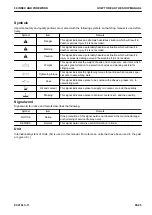
Page 27: ...king posture for slinging work Tightening torque This signal indicates the tightening torque for portions which requires spe cial care in assembling work Coat This signal indicates a place to be coated with adhesive grease etc in assembling work Oil and coolant This signal indicates a place to supply oil coolant etc and the quantity Draining This signal indicates a place to drain oil coolant etc a...

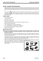
Page 28: ... in good physical condition and good preparation Always be alert and careful General precautions k If the machine is handled incorrectly it is dangerous Read and understand what is described in the operation and maintenance manual before operation Read and understand what is described in this manual before operation Read and understand the meaning of all the safety labels stuck to the machine befo...

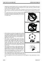
Page 29: ...l levers and hang UNDER REPAIR warning tag on them When performing the disassembling or assembling work support the machine securely with blocks jacks or stands before starting the work Remove all mud and oil from the steps or other places for going up and down on the machine Always use the hand rails ladders or steps when for going up and down on the machine Never jump on or off the machine When ...

Page 30: ... caught in ro tating parts or moving parts When raising a heavy component heavier than 25 kg use a hoist or crane Before starting work check that the slings wire ropes webbing slings chains and hooks are free from damage Always use slings which have ample capacity and install them to proper places Operate the hoist or crane slowly to prevent the component from hitting any other part Do not work wi...

Page 31: ... workers must communicate with each other fre quently The appointed signaler must make specified signals clearly at a place where he is well seen from the operator s seat and where he can see the working condition easily The signaler must always stand in front of the load and guide the operator safely k Never stand under the load k Do not move a load over a person k Never step on the load k Do not...

Page 32: ...ook is maximum at its central part Never use a wire rope which has breaks in strands A re duced diameter B or kinks C There is a danger that the rope may break during the towing operation Precautions for slinging up Wind in the crane slowly until wire ropes are stretched When settling the wire ropes with the hand do not grasp them but press them from above If you grasp them your fingers may be cau...

Page 33: ...to work and passage After operating the hoist do not swing the control switch Remember the position of the main switch so that you can turn off the power immediately in an emer gency If the hoist stops because of a power failure turn off the main switch When turning on a switch after it is turned off by the ground fault circuit interrupter check that the devices related to that switch are not in o...

Page 34: ... to use 2 wrenches use one wrench to fix and use the other one to loosen the nut Precautions for air conditioner piping When installing the air conditioner piping be careful so that dirt dusts and water do not enter the hose Check that the O rings are fitted to the joints when connecting the air conditioner piping Do not reuse an O ring because it is deformed and deteriorated if it is used once Wh...

Page 35: ...ng An O ring is fitted to every joint of the air conditioner piping For tightening torques see THE OTHER INFORMATION Pre cautions for disconnection and connection of air conditioner piping 00 INDEX AND FOREWORD SAFETY NOTICE FOR OPERATION PC210LC 11 00 33 ...

Page 36: ...r attached to or around the engine exhaust manifold muffler or battery or on the undercovers To prevent fires from being caught remove any flammable materials such as dry leaves chips pieces of paper coal dust or any other flammable materials accumulated around the cooling system radiator oil cooler or on the undercover Fire coming from electric wiring Short circuits in the electrical system can c...

Page 37: ...See the Operation and Maintenance Manual for the setting procedure Explosion caused by lighting equipment When checking fuel oil battery electrolyte or coolant always use lighting equipment with anti explosion specifications When taking the electrical power for the lighting equipment from the machine follow the instructions in the Operation and Maintenance Manual 00 INDEX AND FOREWORD PRECAUTIONS ...

Page 38: ...when they are inhaled Do not breathe the fumes After a fire there may be harmful compounds left If they touch your skin they may have a bad influence on your body Be sure to wear rubber gloves when handling the materials left after the fire The material of the gloves which is recommended is polychloroprene Neoprene or polyvinyl chloride in the lower temperature environment When wearing cotton work...

Page 39: ... or lakes Obey appropriate laws and regulations when disposing of harmful objects such as oil fuel coolant solvent filters batteries and DEF Avoid exposure to burning rubber or plastics which produce a toxic gas that is harmful to people When disposing of parts made of rubber or plastics hoses cables and harnesses always comply with the local regulations for disposing industrial waste products 00 ...

Page 40: ... Association of Germany DEF is the abbreviation for Diesel Exhaust Fluid Commercial DEF that is API approved and meets all the requirements defined in ISO 22241 1 This solution will be represented as DEF throughout this manual About DEF DEF is necessary for the urea SCR system DEF is a colorless transparent 32 5 aqueous urea solution Urea as main constituent is a material which is used for cosmeti...

Page 41: ...e When opening the container perform it where there is good ventilation For storage see STORE AdBlue DEF Store AdBlue DEF avoiding direct sunlight Always use the original container at the time of purchase Do not exchange the container of AdBlue DEF with another one If AdBlue DEF is stored in an iron or aluminum con tainer toxic gas may develop and a chemical reaction may corrode the container PREC...

Page 42: ...he remaining pressure from the hydraulic circuit always before performing the work In the field there is a risk of dust entering the component during disassembling or maintenance work and perform ance check is hardly performed Replacement of the as sembly is recommended Perform disassembling and maintenance work in the dust proof area Sealing of openings prevention of flowing out of oil Plug the o...

Page 43: ...MARK Drain the old hydraulic oil not only from the hydraulic tank but also from the filter and drain plug in the cir cuit Avoid reusing the hydraulic oil and lubricating oil Avoid reusing the hydraulic oil and lubricating oil which has been drained from the machine If reused any foreign material may enter the hydraulic equipment and it may cause a failure Flushing operation Flushing is required to...

Page 44: ... can remove the ultra fine approxi mately 3 μm particles that the filter built in the hydraulic equip ment cannot remove So it is very effective device PRECAUTIONS FOR HANDLING HYDRAULIC EQUIPMENT 00 INDEX AND FOREWORD 00 42 PC210LC 11 ...

Page 45: ...ickness and number of shims when storing shims When hoisting the components prepare the slings with sufficient strength When using forcing screws to remove any component tighten the forcing screws uniformly and alternately Before removing any component clean the surrounding area and cover the component to prevent any for eign material from entering after removal After disconnecting the piping or r...

Page 46: ...on of the split flange type hoses and tubes Nomi nal No Bolt pitch mm Hose side Tube side O ring 4 Bolt 5 Washer 6 a b Flange 1 Split flange 2 Sleeve head 3 04 38 1 17 5 07379 00400 07371 30400 07378 10400 07000 12021 01010 80825 01643 50823 05 42 9 19 8 07379 00500 07371 30500 07378 10500 07000 13022 01010 80830 01643 50823 06 47 6 22 2 07379 00640 07371 30640 07378 10600 07000 13025 07372 51035 ...

Page 47: ...01643 51232 30 106 4 62 07379 03010 07371 13010 07378 13000 07000 12085 07372 51650 01643 51645 34 120 6 69 8 07379 03411 07371 13411 07378 13400 07000 12100 07372 51650 01643 51645 40 130 2 77 8 07379 04012 07371 14012 07378 14000 07000 12110 07372 51650 01643 51645 50 152 4 92 07379 05011 07371 15011 07378 15000 07000 12135 07372 51655 01643 51645 Introduction of parts for the removal of O ring ...

Page 48: ...ops of adhesive to the threaded portion When applying liquid gasket clean and degrease the surface and apply it uniformly after making sure that the surface is free from dust or damage Clean all of the parts If there is any damage dents burrs or rust found on them repair it Apply engine oil to the rotating parts and sliding surface Apply molybdenum disulfide lubricant LM P to the surfaces of the p...

Page 49: ... specified amount of grease to the work equipment parts When the coolant is drained be sure that the drain valve is securely tightened then refill the coolant reser voir with the coolant Komatsu recommends to the specified level Start the engine to circulate the coolant in the piping and add the coolant to the specified level again When the hydraulic components are removed and installed refill the...

Page 50: ...ts installation portion If there is any damage replace the part Check that there is no looseness on the exhaust equipment and mounting bolts nuts and clamps on the instal lation portion If there is any looseness retighten the part Check of function of muffler in exhaust system REMARK When an equipment is described as an muffler in exhaust system it is one of the followings The applications or comp...

Page 51: ... necessary to be extremely careful when handling and maintenance of the wiring harnesses If AdBlue DEF is spilled over wiring harness and connectors it may cause corrosion and defective contact Be careful not to spill it over electrical equipment wiring harness and connectors since AdBlue DEF is strongly corrosive to metal Main causes of failure in wiring harness Defective contact of connectors de...

Page 52: ...ricity Entry of water dirt or dust when disconnecting a con nector If any water mud or dust is stuck to the outside surface of a connector it can enter inside the connector when the connector is disconnected Before disconnecting the connector wipe off any stuck water or dirt by using a dry cloth or blow it with compressed air Oil mud or dust stuck to connector If any oil or grease is stuck to the ...

Page 53: ...ay pollute the environ ment Do not discard the oil inconsiderately Ask the customer for disposal or bring it back to dispose it appropriately How to clean parts when dirt is stuck If any dirt or dust sticks the parts of the fuel system clean it off thoroughly with clean fuel Precautions for replacing fuel filter cartridge Be sure to use the Komatsu genuine fuel filter cartridge NOTICE The machine ...

Page 54: ...hen servicing the intake system Select an appropriate workplace Avoid the work of adding hydraulic oil replacing filters or repairing the machine in rainy or windy weather or in dusty environment Sealing the opening Plug the removed pipes and the openings of the removed components with the caps tapes plastic bags etc to prevent foreign material from entering NOTICE Do not expose the openings or st...

Page 55: ...oundness of machine in addition to KOMTRAX function described above These data can be used on per sonal computer screens How to make a full use of KOMTRAX Making use of KOMTRAX enables the following activities Quick response to a request for immediate repair 1 To check the displayed caution and failure code etc through KOMTRAX upon receiving a repair re quest from a user 2 To immediately arrange n...

Page 56: ...sconnection 1 Hold adapter 1 and push hose joint 2 into mating adapter 3 REMARK Push it in approximately 3 5 mm Do not hold rubber cap portion 4 2 While having adapter 3 inserted into hose side joint 2 insert rubber cap 4 to adapter 3 side until it clicks 3 Hold hose adapter 1 or hose 5 and pull it out REMARK Provide an oil container to receive a quantity of hydraulic oil which may flow out Connec...

Page 57: ...Disconnection 1 Hold the tightening adapter part and push body 2 straight until sliding prevention ring 1 contacts contact surface a of the hexagonal part at the male end 2 While keeping the condition of step 1 turn lever 3 to the right clockwise 3 While keeping the conditions of steps 1 and 2 pull out whole body 2 to disconnect it REMARK Provide an container to receive a quantity of hydraulic oil...

Page 58: ...straight until sliding prevention ring 1 contacts contact surface a of the hexagonal part at the male end 2 While keeping the condition of step 1 push cover 3 straight until it contacts contact surface a of the hexago nal portion on the male side 3 While keeping the conditions of steps 1 and 2 pull out whole body 2 to disconnect it REMARK Provide an container to receive a quantity of hydraulic oil...

Page 59: ...ening adapter part and push body 2 straight un til sliding prevention ring 1 contacts contact surface a of the hexagonal part at the male end 00 INDEX AND FOREWORD DISCONNECT AND CONNECT PUSH PULL TYPE COUPLER PC210LC 11 00 57 ...

Page 60: ...with each other when the connec tor is connected When removing a connector from a clip pull the con nector in parallel with the clip as removing stoppers NOTICE If the connector is pried up and down or to the right or left it may break the housing 3 Action to be taken after removing connectors After removing the connector cover it with plastic bags to prevent entry of dust dirt oil or water in the...

Page 61: ...This as a preview PDF file from best manuals com Download full PDF manual at best manuals com ...

Reviews: