background image

A3-30

General Safety & Operation

A03048

To Lower The Dump Body:
(When dumping over a berm or into a crusher):

8. Move the hoist lever forward to the DOWN posi-

tion and release. Releasing the lever places the
hoist control valve in the FLOAT position, allow-
ing the body to return to the frame.

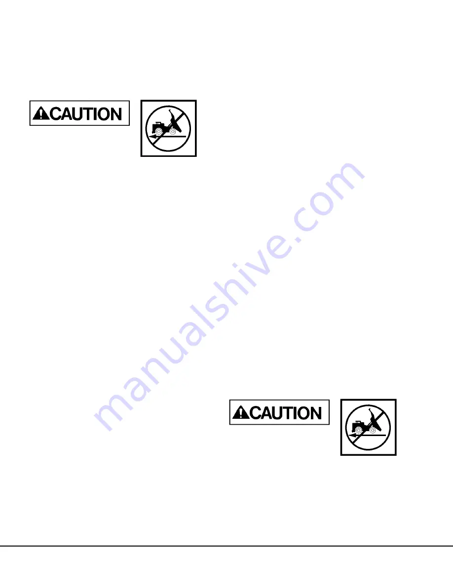
DO NOT drive forward in the
fully raised position if the
dump body will not clear an
obstacle, such as a crusher
wall. DO NOT move the truck with a raised dump
body raised except in an emergency. Failure to
lower the body before moving the truck may
cause damage to the hoist cylinders, frame, and/
or body hinge pins.

NOTE: If the dumped material builds up at the rear of
the truck and the body cannot be lowered, perform
the following steps:

a. Move the hoist lever back to the HOIST posi-

tion and fully raise the dump body. Continue
to hold the hoist lever until the body is com-
pletely raised.

NOTE: If the body is not completely raised, it may
lower very rapidly when the truck is moved forward
and the material is cleared from the rear of the truck.

b. Once the body is fully raised, release the

hoist lever (it will return to the HOLD posi-
tion).

c. Shift the selector switch to FORWARD,

release the brake lock, and press the over-
ride button.

d. Slowly drive forward to clear the material.

e. Once the material is cleared, stop the truck,

place the selector switch in NEUTRAL, and
apply the brake lock.

f. Completely lower the body.

NOTE: Failure to hoist the body, after making an
unsuccessful attempt at lowering the body, may
result in the dump body suddenly lowering after the
truck has pulled ahead of the material that was
previously preventing the body from lowering.

To Lower The Dump Body
(When dumping on flat ground):

9. It is very likely when dumping on flat ground

that the dumped material will prevent the body
from lowering. In this instance, the truck will
have to be driven forward a short distance (just
enough to clear the material) before the body can
be lowered.

a. Shift the selector switch to FORWARD,

release the brake lock, and depress the
override button. Drive forward enough for the
body to clear the material. Stop, shift the
selector switch to NEUTRAL, and apply the
brake lock.

b. Move the hoist lever forward to the DOWN

position and release. Releasing the lever
places the hoist control valve in the FLOAT
position, allowing the body to return to the
frame.

NOTE:  If the dumped material builds up at the rear
of the body and the body cannot be lowered, then
perform steps c and d below: 

c. Move the hoist lever back to the HOIST posi-

tion to fully raise the dump body. Then
release the hoist lever so it returns to the
HOLD position.

d. Shift the selector switch to forward, release

the brake lock, and depress the override but-
ton. Drive forward to clear the material. Stop,
shift the selector switch to NEUTRAL, and
apply the brake lock. Lower the body again.

NOTE: Failure to hoist the body, after making an
unsuccessful attempt at lowering the body, may
result in the dump body suddenly lowering after the
truck has pulled ahead of the material that was
previously preventing the body from lowering.

DO NOT move the truck with a
raised dump body raised
except in an emergency. Fail-
ure to lower the body before
moving the truck may cause damage to the hoist
cylinders, frame, and/or body hinge pins.

10. With the body returned to the frame, move the

selector switch to FORWARD, release the
brake lock, and exit the dump area carefully.

Summary of Contents for 730E

Page 1: ...CEBM024401 Shop Manual DUMP TRUCK SERIAL NUMBERS A30603 A30610 A30616 A30621 A30628 A30629 A30632 ...

Page 2: ...Find manuals at https best manuals com ...

Page 3: ...or maintaining this machine This manual should be kept in or near the machine for reference and periodically reviewed by all personnel who will come into contact with it This material is proprietary to Komatsu America Corp KAC and is not to be reproduced used or dis closed except in accordance with written authorization from KAC It is the policy of the Company to improve products whenever it is po...

Page 4: ...promise the safe operation of Komatsu products and place the operator and others in danger should the part fail Komatsu is also aware of repair companies that will rework or modify an OEM part for reuse in critical systems Komatsu does not generally authorize such repairs or modifications for the same reasons as noted above Use of non OEM parts places full responsibility for the safe performance o...

Page 5: ...text in bold face type such as 135 N m 100 ft lb All torque specifications have 10 tolerance unless otherwise specified A product identification plate is located on the frame in front of the right side front wheel and designates the truck model number product identification number vehicle serial number and maximum GVW Gross Vehicle Weight rating The Komatsu truck model designation consists of thre...

Page 6: ...tential hazard WHICH WILL RESULT in either INJURY OR DEATH if proper precautions are not taken WARNING identifies a specific potential hazard WHICH WILL RESULT in either INJURY OR DEATH if proper precautions are not taken CAUTION is used for general reminders of proper safety practices OR to direct the reader s attention to avoid unsafe or improper practices which may result in damage to the equip...

Page 7: ...OLING AND AIR CLEANER C ELECTRIC SYSTEM 24 VDC NON PROPULSION D ELECTRIC PROPULSION AND CONTROL E DRIVE AXLE SPINDLES AND WHEELS G SUSPENSIONS H BRAKE CIRCUIT J HYDRAULIC SYSTEM L OPTIONS AND SPECIAL TOOLS M OPERATOR S CAB N LUBRICATION AND SERVICE P SYSTEM SCHEMATICS R Find manuals at https best manuals com ...

Page 8: ...A 4 Introduction A00044 KOMATSU MODEL 730E DUMP TRUCK Find manuals at https best manuals com ...

Page 9: ...ERAL INFORMATION INDEX MAJOR COMPONENTS SPECIFICATIONS A2 SAFETY AND OPERATING INSTRUCTIONS A3 WARNINGS AND CAUTIONS A4 TORQUE TABLES AND CONVERSION CHARTS A5 STORAGE AND IDLE MACHINE PREPARATION A7 Find manuals at https best manuals com ...

Page 10: ...A1 2 Index 8 10 A01001 NOTES Find manuals at https best manuals com ...

Page 11: ...s a deluxe interior with a fully adjustable seat with lumbar support a fully adjustable tilt steer ing wheel controls mounted within easy reach of the operator and an analog instrument panel which pro vides the operator with all instruments and gauges which are necessary to control and or monitor the truck s operating systems POWER STEERING The Komatsu 730E dump truck is equipped with a full time ...

Page 12: ... 7 Traction Alternator 8 Cooling Blower 9 Cooling Duct 10 Steering Circuit Filter 11 Hoist Circuit Filter 12 Fuel Tank 13 Hoist Cylinders 14 Rear Axle Housing 15 Drive Motors 16 Rear Hydrair II Suspension 17 Tires 18 Hydraulic Tank 19 SteeringandBrakeCircuitPump 20 Hoist Circuit Pump 21 Accumulators 730E MAJOR COMPONENTS ...

Page 13: ...teries in Series Parallel 220 Ampere Hour Capacity With Disconnect Switch Alternator 24 Volt 140 Ampere Output Lighting 24 Volt Starters 2 24 Volt SERVICE CAPACITIES Liters U S Gallons Crankcase includes lube oil filters Komatsu 223 59 Cooling System 409 108 Fuel 3217 850 Hydraulic System 731 193 Wheel Motor Gear Box 40 Wheel 10 5 Wheel HYDRAULIC SYSTEM Pumps Hoist gear type 513 l min 135 6 GPM at...

Page 14: ...lograms Pounds Front Axle 69 966 154 249 Rear Axle 73 670 162 415 Total 100 fuel 143 636 316 664 Standard Komatsu Body 25 612 56 464 Standard Tire Weight 18 371 40 500 Loaded Vehicle Kilograms Pounds Front Axle 115 655 254 975 Rear Axle 231 343 510 025 Total 346 998 765 000 Nominal Payload 206 408 455 050 Nominal payload is as defined within Komatsu America Corp payload policy documentation Nomi n...

Page 15: ...3 6 ROPS Precautions A3 6 Preventing Injury From Work Equipment A3 6 Precautions For Optional Attachments A3 6 Precautions When Starting The Machine A3 7 PRECAUTIONS FOR TRUCK OPERATION A3 7 Safety Is Thinking Ahead A3 7 Safety At The Work Site A3 7 Fire Prevention A3 7 Preparing For Operation A3 7 Ventilation For Enclosed Areas A3 7 Mirrors Windows And Lights A3 8 In The Operator s Cab Before Sta...

Page 16: ...ce A3 13 Warning Tag A3 13 Proper Tools A3 13 Securing The Dump Body A3 13 DURING MAINTENANCE A3 14 Personnel A3 14 Attachments A3 14 Working Under The Machine A3 14 Keeping The Machine Clean A3 14 Rules To Follow When Adding Fuel Or Oil A3 14 Radiator Coolant Level A3 14 Use Of Lighting A3 14 Precautions With The Battery A3 15 Handling High Pressure Hoses A3 15 Precautions With High Pressure Oil ...

Page 17: ...tion Testing A3 26 Additional Guidelines A3 27 MACHINE OPERATION SAFETY PRECAUTIONS A3 27 LOADING A3 28 HAULING A3 28 PASSING A3 29 DUMPING A3 29 To Raise The Dump Body A3 29 To Lower The Dump Body When dumping over a berm or into a crusher A3 30 To Lower The Dump Body When dumping on flat ground A3 30 TOWING A3 31 Towing Procedure A3 31 SAFE PARKING PROCEDURES A3 32 ENGINE SHUTDOWN PROCEDURE A3 3...

Page 18: ...ing condition Improper use of safety features may result in serious bodily injury or death Clothing And Personal Items Avoid wearing loose clothing jewelry and loose long hair They can catch on controls or in moving parts and cause serious injury or death Additionally DO NOT wear oily clothes as they are flammable Wear a hard hat safety glasses safety shoes mask and gloves when operating or mainta...

Page 19: ...extinguishers are accessible and proper usage techniques are known Provide a first aid kit at the storage point Know what to do in the event of a fire Keep the phone numbers of persons you must contact in case of an emergency Precautions For High Temperature Fluids Immediately after operating the truck engine coolant engine oil and hydraulic oil are at high temperatures and are pressurized If the ...

Page 20: ...regulations and standards for all countries If it is modified or repaired without authorization from Komatsu or is damaged when the machine rolls over the strength of the structure will be compromised and will not be able to fulfill its intended purpose Optimum strength of the structure can only be achieved if it is repaired or modified as specified by Komatsu When modifying or repairing the ROPS ...

Page 21: ...d the work site The operator must personally check the work position the roads to be used and the existence of obstacles before starting the truck Determine the travel roads to be used at the work site Travel roads must be maintained in order to ensure safe machine travel If travel through wet areas is necessary check the depth and flow of water before crossing the shallow parts DO NOT drive throu...

Page 22: ...rease or mud Check the windshield wiper the condition of the wiper blades and the washer fluid reservoir level Be familiar with all steering and brake system controls warning devices road speeds and loading capabilities before operating the truck Seat Belts On both driver and passenger seats check the seat belt fabric buckle all belt retractors and hardware for damage or wear Replace any worn or d...

Page 23: ... shield Stay at least 15 m 50 ft from the tread of the tire In the event of fire in the tire and wheel area including brake fires stay away from the truck for at least eight hours or until the tire and wheel are cool Keep serviceable fire fighting equipment nearby Report used extinguishers for replacement or refilling Apply the parking brake when the truck is parked and unattended DO NOT leave the...

Page 24: ...d before driving Driving with a raised dump body or raising the dump body in an enclosed area may result in serious damage and bodily injury or death Drive with the dump body resting on the frame Driving Near High Voltage Cables Driving near high voltage cables can cause electric shock Maintain the safe distances between the machine and the electric cable as listed below The following actions are ...

Page 25: ...he machine being towed in a straight line with the towing portion of the tow machine Secure it in position DO NOT stand next to the towing device while the truck is moving For more towing information refer to Section 30 Operating Instructions Towing WORKING NEAR BATTERIES Battery Hazard Prevention Battery electrolyte contains sulfuric acid and can quickly burn the skin and eat holes in clothing If...

Page 26: ...he battery disconnect switches to the ON position and attempt starting For booster cable removal disconnect the ground or negative cable first then the 24VDC cable last If any tool touches between the positive terminal and the chassis it will cause sparks Always use caution when using tools near the battery Jump Starting With Receptacles Always wear safety glasses or goggles when starting the mach...

Page 27: ...nal warning tags around the machine if necessary These tags are available from your Komatsu distributor Part No 09963 03001 Proper Tools Use only tools suited to the task Using damaged low quality faulty or makeshift tools can cause personal injury Extra precaution must be used when grinding welding and using a sledgehammer Securing The Dump Body To avoid serious personal injury or death the body ...

Page 28: ...und the doors or vents DO NOT allow any water to enter the cooling air inlet duct above the electrical control cabinet If water enters the control cabinet through any opening or crevice major damage to the electrical components may occur DO NOT spray water into the rear wheel electric motor covers Damage to the wheel motor armatures may occur DO NOT spray water into the retarding grids Excess wate...

Page 29: ...glasses and thick gloves Use a piece of cardboard or a sheet of wood to check for oil leakage Maintenance Near High Temperatures And High Pressures Immediately after stopping the engine coolant and operating oils are at high temperature and may be pressurized In these conditions opening the system or replacing the filters may result in burns or other injury Wait for the temperature to cool and the...

Page 30: ... the following 1 A wheel cage or other restraining device that will constrain all wheel rim components during an explosive separation of a multi piece wheel rim or during the sudden release of air 2 A stand off inflation device which permits a per son to stand outside of the potential trajectory of the wheel components Use the specified tires The tire inflation pressure and permissible speeds give...

Page 31: ...g when inflating a tire mounted on the machine Observers must not be permitted in the area DO NOT weld or heat the rim assembly with the tire mounted on the rim Resulting gases inside the tire may ignite causing explosion of the tire and rim Storing Tires After Removal As a basic rule store the tires in a warehouse in which unauthorized persons cannot enter If the tires are stored outside erect a ...

Page 32: ...__________________________________________________ _______________________________________________________________________________________ _______________________________________________________________________________________ _______________________________________________________________________________________ _____________________________________________________________________________________...

Page 33: ...r lead wire and isolate the elec tronic control components before making the welding repairs It is not necessary to disconnect or remove any control circuit cards or any of the Alarm Indicating Device AID circuit control cards Fasten the welding machine ground lead to the piece being welded the grounding clamp must be attached as near as possible to the weld area DO NOT allow welding current to pa...

Page 34: ...tted the operator must follow this or a similar routine 1 Start at the left front of the truck During the walk around inspection visually inspect all lights and safety equipment for external dam age Ensure all light housing lenses are clean and unbroken 2 Empty the dust pans on the left side air clean ers Ensure the battery box covers are in place and securely fastened Inspect the battery box cove...

Page 35: ...action Alternator 8 Cooling Blower 9 Cooling Duct 10 Steering Circuit Filter 11 Hoist Circuit Filter 12 Fuel Tank 13 Hoist Cylinders 14 Rear Axle Housing 15 Drive Motors 16 Rear Hydrair II Suspension 17 Tires 18 Hydraulic Tank 19 SteeringandBrakeCircuitPump 20 Hoist Circuit Pump 21 Accumulators FIGURE 3 3 COMPONENT LOCATION ...

Page 36: ... the area for any oil leakage from inside the wheel cover could indicate brake or wheel motor leakage Inspect the dual tires for damage Verify proper inflation pressure If the truck has been operat ing with low tire pressure the tire must be cooled before parking the truck inside 14 Move to the rear of the dual tires Check for and remove any rocks lodged between the dual tires To prevent tire dama...

Page 37: ... Inspect the mounting key area for evidence of wear Verify the suspension extension exposed piston rod is correct Check for leaks Check for leaks around the hub and brakes Also check for any unusual wear conditions or damage Ensure the rod end of the steering cylinder is properly greased Verify all mounting hardware is properly tightened Check for any hydraulic leaks 25 Move outboard of the front ...

Page 38: ...ore any personal gear in the cab so it does not interfere with the operation of the truck DO NOT carry tools or supplies in the cab of the truck or on the deck 35 Adjust the seat and steering wheel so that it is comfortable for use 36 Read and understand the Operator Controls and Instrument Panel discussion in this section Be familiar with all the control locations and functions before operating t...

Page 39: ...s tems are normal test the truck steering in extreme right and left directions If the steering system is not operating properly shut the engine off immediately Determine the steering system problem and repair before resuming operation 2 Check the brakes before moving the truck Start the engine and allow the hydraulic system to fully pressurize Activate the service brake park ing brake and brake lo...

Page 40: ...move there is no hydraulic pressure 3 Check the hydraulic tank oil level The oil level must be visible in the center of the upper sight glass and must not cover the entire upper sight glass Add oil if necessary DO NOT overfill 4 Turn the key switch to the ON position but DO NOT start the engine a Steering system pressure Verify that the low steering pressure warning light is illuminated If it is n...

Page 41: ...ystems are functioning properly the operator must follow all the local safety rules to ensure safe machine operation If any of the red warning lights come on or if any gauge reads in the red area during truck opera tion a malfunction is indicated Stop the truck as soon as safety permits shut the engine off and have the problem corrected before resuming truck operation Operating the truck with stal...

Page 42: ...imes if the truck is in motion or unattended 2 Obey all road signs Operate the truck in a con trolled manner Govern the truck speed by the road conditions weather and visibility Report haul road conditions immediately Muddy or icy roads pot holes or other obstructions can pres ent hazards 3 When backing the truck give the back up signal three sounds of the horn When starting for ward two sounds of...

Page 43: ...ol is unmodulated and applies the rear service brakes only 3 When the truck is stopped and in the dump position apply the wheel brake lock Move the selector switch to the NEUTRAL position To Raise The Dump Body Dumping certain types of material can result in sudden and violent movement of the truck This truck movement may cause injury to the opera tor It may also cause damage to the hoist cylin de...

Page 44: ...iously preventing the body from lowering To Lower The Dump Body When dumping on flat ground 9 It is very likely when dumping on flat ground that the dumped material will prevent the body from lowering In this instance the truck will have to be driven forward a short distance just enough to clear the material before the body can be lowered a Shift the selector switch to FORWARD release the brake lo...

Page 45: ... weight of truck being towed Install tow bar between the two vehicles 5 Block the wheels on the tow vehicle to prevent movement while preparing the disabled truck for towing 6 If necessary install quick disconnect fittings to the bleeddown manifold to allow the hydraulic system to be operational Install hydraulic connections for steering braking between the tow vehicle the and disabled vehicle An ...

Page 46: ...e shutdown switch on the center console see Operator Controls section 4 With the key switch OFF and the engine stopped wait at least 90 seconds Ensure the pressure is relieved in the steering circuit by turning the steering wheel back and forth sev eral times No front wheel movement will occur when hydraulic pressure is relieved 5 Close and lock all windows remove the key from the key switch and l...

Page 47: ...afely as possible after the loss of engine power If the brake supply pressure drops to a pre deter mined level the low brake pressure warning light will illuminate and a buzzer will sound If the brake pres sure continues to decrease the auto apply feature will activate and the service brakes will apply auto matically to stop the truck 1 Bring the truck to a safe stop as quickly as pos sible by usi...

Page 48: ...A3 34 General Safety Operation A03048 NOTES ...

Page 49: ... tamper preventative symbols The remaining 17 alpha numeric characters are used to identify five characteristics of the machine The five characteristics are detailed below WMC Character positions 1 2 and 3 identify the Worldwide Manufacturer Code WMC The WMC designates the manufacturer of the product Komatsu brand products are identified with the letters KMT MDS Character positions 4 5 6 7 and 8 i...

Page 50: ...s the importance of reading the operator s manual before operation A plate attached to the right rear corner of the cab states the Rollover Protective Structure ROPS and Falling Object Protective Structure FOPS meet vari ous SAE performance requirements DO NOT make modifications to the ROPS compo nents DO NOT attempt to repair damage without written approval from the manufacturer Unau thorized rep...

Page 51: ...This as a preview PDF file from best manuals com Download full PDF manual at best manuals com ...

Reviews: