background image

FOREWORD

EXPLANATION OF TERMS FOR MAINTENANCE STANDARD

WB142-5

00-9 

d

After repairing or replacing some parts, measure the size of their hole and shaft and check that the interference is in
the standard range.

4.

Repair limit and allowable value

The size of a part changes because of wear and deformation while it is used. The limit of changed size is called the
"repair limit."

If a part is worn to the repair limit must be replaced or repaired.

The performance and function of a product lowers while it is used. A value below which the product can be used
without causing a problem is called the "allowable value."

If a product is worn to the allowable value, it must be checked or repaired. The permissible value is estimated from
various tests or experiences in most cases, however, it must be judged after considering the operating condition and
customer's requirement.

5.

Clearance limit

Parts can be used until the clearance between them is increased to a certain limit. The limit at which those parts 
cannot be used is called the "clearance limit."

If the clearance between the parts exceeds the clearance limit, they must be replaced or repaired.

6.

Interference limit

The allowable maximum interference between the hole of a part and the shaft of another part to be assembled is called
the "interference limit."

The interference limit shows the repair limit of the part of smaller tolerance.

If the interference between the parts exceeds the interference limit, they must be replaced or repaired.

Summary of Contents for A13001

Page 1: ...t is our policy to improve our products whenever it is possible and practical to do so We reserve the right to make changes or add improvements at any time without incurring any obligation to install...

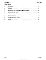
Page 2: ...FOREWORD 00 1 01 GENERAL 01 1 10 STRUCTURE FUNCTION AND MAINTENANCE STANDARD 10 1 20 STANDARD VALUE TABLE 20 1 30 TESTING AND ADJUSTING 30 1 40 TROUBLESHOOTING 40 1 50 DISASSEMBLY AND ASSEMBLY 50 1 90...

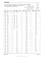
Page 3: ...00 19 d 00 20 d 00 21 d 00 22 d 00 23 d 00 24 d 01 1 d 01 2 d 01 3 d 01 4 d 01 5 d 01 6 d 01 7 d 01 8 d 01 9 d 01 10 d 10 1 10 2 10 3 10 4 10 5 10 6 10 7 10 8 10 9 10 10 10 11 10 12 10 13 b 10 14 b 10...

Page 4: ...40 27 d 40 28 d 40 29 d 40 30 d 50 1 d 50 2 d 50 3 d 50 4 d Mark Page Rev 50 5 d 50 6 d 50 7 d 50 8 d 50 9 d 50 10 d 50 11 d 50 12 d 50 13 d 50 14 d 50 15 d 50 16 d 50 17 d 50 18 d 50 19 d 50 20 d 50...

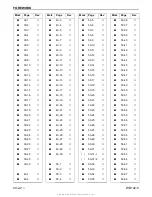
Page 5: ...50 128 d 50 129 d 50 130 d 50 131 d 50 132 d 50 133 d 50 134 d Mark Page Rev 50 135 d 50 136 d 50 137 d 50 138 d 50 139 d 50 140 d 50 141 d 50 142 d 50 143 d 50 144 d 50 145 d 50 146 d 50 147 d 50 14...

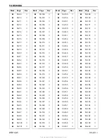
Page 6: ...d 50 256 d 50 257 d 50 258 d 50 259 d 50 260 d 50 261 d 50 262 d 50 263 d 50 264 d 50 265 d 50 266 d Mark Page Rev 50 267 d 50 268 d 50 269 d 50 270 d 50 271 d 50 272 d 50 273 d 50 274 d 50 275 d 50...

Page 7: ...FOREWORD WB142 5 00 2 5 d 90 10 90 11 90 12 90 13 90 14 90 15 90 16 90 17 90 18 Mark Page Rev Mark Page Rev Mark Page Rev Mark Page Rev Find manuals at https best manuals com...

Page 8: ...FOREWORD 00 2 6 d WB142 5 Mark Page Rev Mark Page Rev Mark Page Rev Mark Page Rev Find manuals at https best manuals com...

Page 9: ...ork equipment to the ground If this is not possi ble insert the safety pin or use blocks to prevent the work equipment from falling In addition be sure to lock all the control levers and hang warning...

Page 10: ...l not be damaged by contact with other parts when the machine is being operated 10 When installing high pressure hoses be sure that they are not twisted Damaged tubing is dangerous Be extremely carefu...

Page 11: ...f the structure but also serves as reference material for troubleshooting In addition this section gives the judgement standards when inspecting disassembled parts STANDARD VALUE TABLES This section e...

Page 12: ...ber for each item 3 Additional pages Additional pages are indicated by a hyphen and numbered after the page number File as in the example Example REVISED EDITION MARK 00 When a manual is revised an ed...

Page 13: ...subjected to each rope will increase with the hanging angles The table below shows the variation of allowable load when hoisting with two ropes each of which is allowed to sling up to 1000 kg 2205 lb...

Page 14: ...s of the hole and shaft The tightness of fit is decided by the tolerance Indication of size of rotating shaft and hole and relationship drawing of them 2 Standard clearance and standard value The clea...

Page 15: ...able value it must be checked or repaired The permissible value is estimated from various tests or experiences in most cases however it must be judged after considering the operating condition and cus...

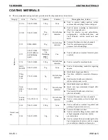
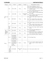
Page 16: ...250 g Polyethylene container Used as sealant for machined holes Holtz MH 705 790 126 9120 75 g Tube Used as heat resisting sealant for repairing engine Three bond 1735 179 129 9140 2 g Polyethylene co...

Page 17: ...type Used as sealant for flywheel housing intake manifold oil pan thermostat housing etc Three bond 1211 790 129 9090 100 g Tube Used as heat resisting sealant for repairing engines Molybdenum disulp...

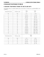
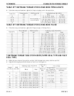
Page 18: ...2 1 4 9 7 1 0 8 13 31 4 2 9 23 2 2 1 10 17 65 7 6 8 48 5 5 0 12 19 112 9 8 82 6 7 2 14 22 177 19 130 5 14 0 16 24 279 29 205 8 23 4 18 27 383 39 282 5 28 8 20 30 549 58 404 9 42 8 22 32 745 78 549 5...

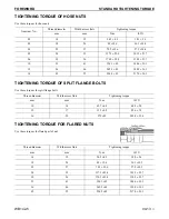
Page 19: ...36 1 14 4 04 22 27 78 5 19 6 57 9 14 4 05 24 32 137 3 29 4 101 3 21 7 06 30 36 176 5 29 4 130 2 21 7 10 33 41 196 1 49 144 6 36 1 12 36 46 245 2 49 180 9 36 1 14 42 55 294 2 49 217 0 36 1 Thread diam...

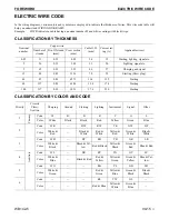
Page 20: ...mm Range Target 08 08 14 5 88 8 82 4 33 6 50 7 35 5 42 10 10 17 9 8 12 74 7 22 9 39 11 27 8 31 12 12 19 14 7 19 6 10 84 14 45 17 64 13 01 14 14 22 19 6 24 5 14 45 18 07 22 54 16 62 16 16 24 24 5 34 3...

Page 21: ...etc 5 65 0 32 5 23 4 6 37 Charging and signal 15 84 0 45 13 36 7 0 59 Starting Glow plug 40 85 0 80 42 73 11 4 135 Starting 60 127 0 80 63 84 13 6 178 Starting 100 217 0 80 109 1 17 6 230 Starting Pri...

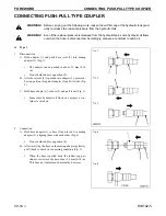
Page 22: ...d hose adapter 1 or hose 5 and insert it in mating adapter 3 aligning them with each other Fig 4 Do not hold rubber cap portion 4 B After inserting the hose in the mating adapter perfectly pull it bac...

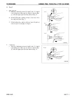
Page 23: ...a of the hexagonal portion at the male end Fig 6 B While holding the condition of Step A turn lever 8 to the right clockwise Fig 7 C While holding the condition of Steps A and B pull out whole body 7...

Page 24: ...t the male end Fig 10 B While holding the condition of Step A push cover 10 straight until it contacts surface b of the hexagonal por tion at the male end Fig 11 C While holding the condition of Steps...

Page 25: ...the table so divide by 10 move the decimal one place to the left to convert it to 55 mm B Carry out the same procedure as above to convert 55 mm to 2 165 inches C The original value 550 mm was divide...

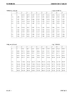
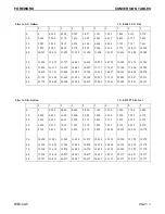
Page 26: ...8 3 307 3 346 3 386 3 425 3 465 3 504 90 3 543 3 583 3 622 3 661 3 701 3 740 3 780 3 819 3 858 3 898 Kilogram to Pound 1 kg 2 2046 lb 0 1 2 3 4 5 6 7 8 9 0 0 2 20 4 41 6 61 8 82 11 02 13 23 15 43 17 6...

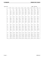
Page 27: ...662 21 926 22 190 22 455 22 719 22 983 23 247 23 511 90 23 775 24 040 24 304 24 568 24 832 25 096 25 361 25 625 25 889 26 153 Liter to U K Gallon 1 l 0 21997 U K Gal 0 1 2 3 4 5 6 7 8 9 0 0 0 220 0 4...

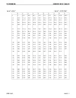
Page 28: ...0 3 607 6 614 8 622 0 629 3 636 5 643 7 90 651 0 658 2 665 4 672 7 679 9 687 1 694 4 701 6 708 8 716 1 100 723 3 730 5 737 8 745 0 752 2 759 5 766 7 773 9 781 2 788 4 110 795 6 802 9 810 1 817 3 824 6...

Page 29: ...1294 1309 1323 1337 1351 1365 1380 1394 1408 100 1422 1437 1451 1465 1479 1493 1508 1522 1536 1550 110 1565 1579 1593 1607 1621 1636 1650 1664 1678 1693 120 1707 1721 1735 1749 1764 1778 1792 1806 182...

Page 30: ...66 2 12 2 54 129 2 31 7 89 192 2 26 1 15 5 0 6 7 20 68 0 12 8 55 131 0 32 2 90 194 0 25 6 14 6 8 6 1 21 69 8 13 3 56 132 8 32 8 91 195 8 25 0 13 8 6 5 6 22 71 6 13 9 57 134 6 33 3 92 197 6 24 4 12 10...

Page 31: ...SYSTEM 01 4 SERVICE REFILL CAPACITIES 01 4 TRANSMISSION 01 5 TOTAL MASS 01 5 STANDARD BUCKET CAPACITY 01 5 LOADER 01 5 TIRE PRESSURE 01 5 WEIGHT TABLE 01 6 FUEL COOLANT AND LUBRICANTS 01 7 PROPER SEL...

Page 32: ...Digging depth 2 level bottom 4276mm 14 0 E Reach at maximum height and 45o dump angle 910mm 3 0 Q Reach at maximum height 2640mm 8 8 F Dumping angle 45o R Maximum reach 5580mm 18 4 G Rollback angle 45...

Page 33: ...GENERAL SPECIFICATION DRAWING WB142 5 01 3 3 BACKHOE ARM...

Page 34: ...ystem Direct injection Air cleaner Dry type with safety element Lubrication system Method Gear pump force lubrication Filter Full flow Cooling system Type Radiator water cooled system Starting system...

Page 35: ...11 351 lb Arm breakout force 3 550 kg 7 670 lb Front bucket capacity SAE 0 77 m3 1 0 yd3 Backhoe bucket capacity SAE 0 20 m3 0 24 yd3 LOADER Standard bucket width 2 180 mm 7 ft 2 in Standard bucket ca...

Page 36: ...n 232 511 Front axle 262 578 Rear axle 430 948 Front wheel complete with rim 52 115 Rear wheel complete with rim 126 357 Work equipment front loader 1 100 2 425 Boom 313 690 Bucket 436 961 Bucket cyli...

Page 37: ...5W 40 Hydraulic system SAE 5W 97 liter 25 6 gal 41 liter 10 8 gal SAE 10W SAE 30 SAE 10W 30 Hydraulic system with biodegradable oil 97 liter 25 6 gal 41 liter 10 8 gal See page 3 12 Front axle Differe...

Page 38: ...even though an atmospheric temperature goes up to 10 C 18 F more or less in the day time Use API classification CI 4 There is no problem if single grade oil is mixed with multigrade oil SAE10W 30 10W...

Page 39: ...INE UNISYN HLP 32 68 It Is not possible to mix the synthetic biodegradable oil type HEES with ordinary hydraulic oils since when the temperature increases insoluble compounds are generated which are d...

Page 40: ...GENERAL LUBRICATION DIAGRAMS 01 10 3 WB142 5 12 LUBRICATION DIAGRAMS GENERAL VIEW Remark Use only recommended oil and grease...

Page 41: ...This as a preview PDF file from best manuals com Download full PDF manual at best manuals com...

Reviews: