background image

Precautions for using overhead traveling crane

k

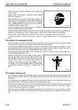
 When raising a component heavier than 25 kg), use a hoist or crane.

REMARK

Weight of component which is heavier than 25 kg is shown with symbol 

 in "DISASSEMBLY AND ASSEM-

BLY".

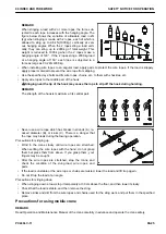
• Before starting work, check the wire ropes, brake, clutch, controller, rails, over winding prevention device,

ground fault circuit interrupter for electric shock prevention, crane collision prevention device, and energiz-

ing caution lamp, and check the following safety items.

• Observe the signals for sling work.
• Operate the hoist at a safe place.
• Be sure to check the directions of the direction indication plate (north, south, east and west) and the

operating button.

• Do not sling a load at an angle. Do not move the crane while the slung load is swinging.
• Do not raise or lower a load while the crane is moving longitudinally or laterally.
• Do not drag a sling.
• When lifting up a load, stop it just after it becomes off the ground, check the safety, and then lift it up.
• Consider the travel route in advance and lift up a load to a safe height.
• Place the control switch in a position where it is not an obstacle to work and passage.
• After operating the hoist, do not swing the control switch.
• Remember the position of the main switch so that you can turn off the power immediately in an emer-

gency.

• If the hoist stops because of a power failure, turn off the main switch. When turning on a switch after it

is turned off by the ground fault circuit interrupter, check that the devices related to that switch are not

in operating condition.

• If you find an obstacle around the hoist, stop the operation.
• After finishing the work, stop the hoist at the specified position and raise the hook to at least 2 m above

the floor. Do not leave the sling installed to the hook.

Selecting wire ropes

Select adequate ropes depending on the weight of the parts to be hoisted referring to the table below.

REMARK

The allowable load is calculated with one sixth (safety factor 6) of the breaking load of the rope.

Wire rope (JIS G3525 6x37-A type) (Standard Z twist wire ropes without galvanizing)

Nominal diameter of rope ( mm)

Allowable load ( kN { t} )

10

8.8 {0.9}

12

12.7 {1.3}

14

17.3 {1.7}

16

22.6 {2.3}

18

28.6 {2.9}

20

35.3 {3.6}

25

55.3 {5.6}

30

79.6 {8.1}

40

141.6 {14.4}

50

221.6 {22.6}

SAFETY NOTICE FOR OPERATION

00 INDEX AND FOREWORD

00-26

PC240LC-11

Summary of Contents for A22001

Page 1: ...icy to improve our products whenever it is possible and practical to do so We reserve the right to make changes or improvements at any time without incurring any obligation to install such changes on...

Page 2: ...Find manuals at https best manuals com...

Page 3: ...00 INDEX AND FOREWORD PC240LC 11 00 1 Find manuals at https best manuals com...

Page 4: ...FOR DISCONNECTING AND CONNECTING CONNECTOR WITH LOCK TO PUSH 00 61 METHOD FOR DISCONNECTING AND CONNECTING CONNECTOR WITH HOUSING TO ROTATE 00 63 HOW TO READ ELECTRICAL WIRE CODE 00 64 EXPLANATION OF...

Page 5: ...M 10 288 TRAVEL CONTROL SYSTEM DIAGRAM 10 292 COMPONENT PARTS OF TRAVEL SYSTEM 10 294 UNDERCARRIAGE AND FRAME 10 315 LAYOUT DRAWING OF UNDERCARRIAGE 10 315 WORK EQUIPMENT 10 317 STRUCTURE OF WORK EQUI...

Page 6: ...UST OIL PRESSURE IN PUMP LS CONTROL CIRCUIT 30 100 TEST OUTLET PRESSURE OF SOLENOID VALVE 30 107 TEST PPC VALVE OUTLET PRESSURE 30 111 ADJUST WORK EQUIPMENT AND SWING PPC VALVES 30 113 TEST PUMP SWASH...

Page 7: ...N6 Abrupt Engine Stop by Auto Idling Stop 1 40 181 FAILURE CODE A900NY Abrupt Engine Stop by Auto Idling Stop 2 40 182 FAILURE CODE AA10NX Air Cleaner Clogging 40 183 FAILURE CODE AB00KE Charge Voltag...

Page 8: ...ssure High Error 2 40 277 FAILURE CODE CA451 Common Rail Pressure Sensor High Error 40 278 FAILURE CODE CA452 Common Rail Pressure Sensor Low Error 40 280 FAILURE CODE CA488 Charge Air Temperature Hig...

Page 9: ...id Open Circuit Error 40 388 FAILURE CODE CA2353 EGR Valve Solenoid Short Circuit Error 40 391 FAILURE CODE CA2357 EGR Valve Servo Error 40 393 FAILURE CODE CA2381 KVGT Position Sensor High Error 40 3...

Page 10: ...elay 1 Voltage High Error 40 521 FAILURE CODE CA3563 AdBlue DEF Line Heater Relay 1 Voltage Low Error 40 523 FAILURE CODE CA3567 AdBlue DEF Injector Open Circuit Error or Short Circuit Error 40 526 FA...

Page 11: ...CA4281 SCR NH3 Sensor Stuck Response Error 40 665 FAILURE CODE CA4459 AdBlue DEF Line Heater Relay 2 Voltage High Error 40 668 FAILURE CODE CA4461 AdBlue DEF Line Heater Relay 2 Voltage Low Error 40...

Page 12: ...ve Function 40 797 FAILURE CODE DHSDMA Bucket DUMP PPC Pressure Sensor Defective Function 40 800 FAILURE CODE DHSFMA Travel Forward Left PPC Pressure Sensor Defective Function 40 803 FAILURE CODE DHSG...

Page 13: ...enoid Open Circuit 40 916 FAILURE CODE DXE9KB Attachment Flow Regulating EPC 4 Solenoid Short Circuit 40 918 FAILURE CODE DXE9KY Attachment Flow Regulating EPC 4 Hot Short Circuit 40 920 FAILURE CODE...

Page 14: ...82 E 32 ALARM BUZZER CANNOT BE CANCELED 40 984 E 33 SERVICE METER IS NOT DISPLAYED WHILE STARTING SWITCH IS IN OFF POSITION 40 985 E 34 SERVICE MODE CANNOT BE SELECTED 40 986 E 35 ALL OF WORK EQUIPMEN...

Page 15: ...HAVING HEAVIER LOAD MOVES SLOWER 40 1064 H 15 TIME LAG OF WORK EQUIPMENT IS LARGE 40 1065 H 16 MACHINE DOES NOT TRAVEL STRAIGHT 40 1066 H 17 MACHINE IS HARD TO STEER OR TRAVEL POWER IS LOW 40 1068 H...

Page 16: ...40 1122 S 25 THERE IS UNUSUAL SMELL IRRITATING ODOR 40 1124 S 26 FOREIGN MATERIALS ENTER AdBlue DEF AdBlue DEF INCREASES 40 1125 50 DISASSEMBLY AND ASSEMBLY 50 1 CONTENTS 50 2 RELATED INFORMATION ON...

Page 17: ...COUNTERWEIGHT ASSEMBLY 50 343 HYDRAULIC SYSTEM 50 350 REMOVE AND INSTALL CENTER SWIVEL JOINT ASSEMBLY 50 350 DISASSEMBLE AND ASSEMBLE CENTER SWIVEL JOINT ASSEMBLY 50 355 REMOVE AND INSTALL HYDRAULIC T...

Page 18: ...ARD OF CONTROL VALVE 60 35 MAINTENANCE STANDARD OF WORK EQUIPMENT AND SWING PPC VALVE 60 45 MAINTENANCE STANDARD OF TRAVEL PPC VALVE 60 48 MAINTENANCE STANDARD OF 1ST LINE ATTACHMENT PPC VALVE WITH EP...

Page 19: ...Air Temperature Sensor Short Circuit 80 54 FAILURE CODE 879BKA A C Fresh Air Temperature Sensor Open Circuit 80 55 FAILURE CODE 879BKB A C Fresh Air Temperature Sensor Short Circuit 80 57 FAILURE COD...

Page 20: ...DIAGRAM 3 7 90 17 ELECTRICAL CIRCUIT DIAGRAM 4 7 90 19 ELECTRICAL CIRCUIT DIAGRAM 5 7 90 21 ELECTRICAL CIRCUIT DIAGRAM 6 7 90 23 ELECTRICAL CIRCUIT DIAGRAM 7 7 90 25 INDEX 1 INDEX 00 INDEX AND FOREWOR...

Page 21: ...in troubleshooting 30 TESTING AND ADJUSTING This section describes the measuring tools and measuring methods for testing and adjusting as well as the ad justing method of each part The standard value...

Page 22: ...icates the tightening torque for portions which requires spe cial care in assembling work Coat This signal indicates a place to be coated with adhesive grease etc in assembling work Oil and coolant Th...

Page 23: ...physical condition and preparation Always be alert and careful General precautions k If the machine is handled incorrectly it is dangerous Read and understand what is described in the Operation and Ma...

Page 24: ...levers and hang UNDER REPAIR warning tag on them When performing the disassembling or assembling work support the machine securely with blocks jacks or stands before starting the work Remove all mud...

Page 25: ...e of a spring always leave 2 bolts in di agonal positions Loosen those 2 bolts gradually and alter nately to release the pressure and then remove the part When removing components do not break or dama...

Page 26: ...e the operator safely k Never stand under the load k Do not move a load over a person k Never stand under the load k Do not prevent the load from swinging or falling down by holding it simply with the...

Page 27: ...ng REMARK The strength of the hook is maximum at its central part Never use a wire rope which has breaks in strands A re duced diameter B or kinks C There is a danger that the rope may break during th...

Page 28: ...he control switch in a position where it is not an obstacle to work and passage After operating the hoist do not swing the control switch Remember the position of the main switch so that you can turn...

Page 29: ...ner hoses and tubes be sure to use 2 wrenches use one wrench to fix and use the other one to loosen the nut Precautions for air conditioner piping When installing the air conditioner piping be careful...

Page 30: ...g An O ring is fitted to every joint of the air conditioner piping For tightening torques see THE OTHER INFORMATION Pre cautions for disconnection and connection of air conditioner piping SAFETY NOTIC...

Page 31: ...umulated or attached to or around the engine exhaust manifold muffler or battery or on the undercovers To prevent fires from being caught remove any flammable materials such as dry leaves chips pieces...

Page 32: ...ee the Operation and Maintenance Manual for the setting procedure Explosion caused by lighting equipment When checking fuel oil battery electrolyte or coolant always use lighting equipment with anti e...

Page 33: ...ody when they are sucked Do not breathe a fume After a fire there may be harmful compounds left If it touches your skin it may have a bad influence on your body Be sure to wear rubber gloves when hand...

Page 34: ...or lakes Obey appropriate laws and regulations when disposing of harmful objects such as oil fuel coolant solvent filters batteries and DEF Avoid exposure to burning rubber or plastics which produce a...

Page 35: ...Association of Germany DEF is the abbreviation for Diesel Exhaust Fluid Commercial DEF that is API approved and meets all the requirements defined in ISO 22241 1 This solution will be represented as D...

Page 36: ...When opening the container perform it where there is good ventilation For storage see STORE AdBlue DEF Store AdBlue DEF avoiding direct sunlight Always use the original container at the time of purch...

Page 37: ...ax 10 C Up to 36 months Max 25 C Up to 18 months Max 30 C Up to 12 months Max 35 C Up to 6 months Do not store AdBlue DEF in the temperature of 35 C or above Handling AdBlue DEF in cold weather AdBlue...

Page 38: ...aling of openings prevention of flowing out of oil Plug the openings of the piping and the device which have been removed to prevent foreign material from enter ing and oil from flowing out NOTICE Do...

Page 39: ...required to completely dislodge the contami nants and sludges and existing oil containing those inside the hydraulic circuit after disassembling and assembling and when replacing the oil with the new...

Page 40: ...ckness and number of shims when storing shims When hoisting the components prepare the slings with sufficient strength When using forcing screws to remove any component tighten the forcing screws unif...

Page 41: ...f the split flange type hoses and tubes Nomi nal No Shoe bolt pitch mm Hose side Tube side O ring 4 Bolt 5 Washer 6 a b Flange 1 Split flange 2 Sleeve head 3 04 38 1 17 5 07379 00400 07371 30400 07378...

Page 42: ...01643 51232 30 106 4 62 07379 03010 07371 13010 07378 13000 07000 12085 07372 51650 01643 51645 34 120 6 69 8 07379 03411 07371 13411 07378 13400 07000 12100 07372 51650 01643 51645 40 130 2 77 8 073...

Page 43: ...ps of adhesive to the threaded portion When applying liquid gasket clean and degrease the surface and apply it uniformly after making sure that the surface is free from dust or damage Clean all of the...

Page 44: ...ease to the work equipment parts When the coolant is drained be sure that the drain valve is securely tightened then refill the coolant reser voir with the coolant Komatsu recommends to the specified...

Page 45: ...its installation portion If there is any damage replace the part Check that there is no looseness on the exhaust equipment and mounting bolts nuts and clamps on the instal lation portion If there is...

Page 46: ...necessary to be extremely careful when handling and maintenance of the wiring harnesses If AdBlue DEF is spilled over wiring harness and connectors it may cause corrosion and defective contact Be care...

Page 47: ...icity Entry of water dirt or dust when disconnecting a con nector If any water mud or dust is stuck to the outside surface of a connector it can enter inside the connector when the connector is discon...

Page 48: ...y pollute the environ ment Do not discard the oil inconsiderately Ask the customer for disposal or bring it back to dispose it appropriately How to clean parts when dirt is stuck If any dirt or dust s...

Page 49: ...l when servicing the intake system Select an appropriate workplace Avoid the work of adding hydraulic oil replacing filters or repairing the machine in rainy or windy weather or in dusty environment S...

Page 50: ...practically KOMTRAX enables the following support activities Quick response to a request for immediate repair 1 Check the displayed caution and failure code etc through KOMTRAX upon receiving a repai...

Page 51: ...connection 1 Hold adapter 1 and push hose joint 2 into mating adapter 3 REMARK Push it in approximately 3 5 mm Do not hold rubber cap portion 4 2 While having adapter 3 inserted into hose side joint 2...

Page 52: ...isconnection 1 Hold the tightening adapter part and push body 2 straight until sliding prevention ring 1 contacts contact surface a of the hexagonal part at the male end 2 While keeping the condition...

Page 53: ...traight until sliding prevention ring 1 contacts contact surface a of the hexagonal part at the male end 2 While keeping the condition of step 1 push cover 3 straight until it contacts contact surface...

Page 54: ...ning adapter part and push body 2 straight un til sliding prevention ring 1 contacts contact surface a of the hexagonal part at the male end DISCONNECT AND CONNECT PUSH PULL TYPE COUPLER 00 INDEX AND...

Page 55: ...ith each other when the connec tor is connected When removing a connector from a clip pull the con nector in parallel with the clip as removing stoppers NOTICE If the connector is pried up and down or...

Page 56: ...protrusion of the boot and misalignment of the wiring harness If the connector is with the boot correct any extrusion of the boot In addition if the wiring harness is misaligned or the clamp is out of...

Page 57: ...lated parts from becoming too hot as this will cause deformation or damage to the connector 3 Perform a continuity test on the connector After drying leave the wiring harness disconnected and perform...

Page 58: ...fore disconnecting or connecting the connectors Before performing troubleshooting check all the related connectors for loose connection REMARK Check the related connectors for their performance by dis...

Page 59: ...Push in female connector 2 horizontally and insert it straight until it clicks Arrow x 2 In order to check whether locks a and b are completely inserted insert female connector 2 by rocking it vertica...

Page 60: ...and if connector 1 does not come out when it is pulled toward you push up portion A with a small flat head screwdriver while pressing lock L2 and then pull out connector 1 to ward you Method for conn...

Page 61: ...This as a preview PDF file from best manuals com Download full PDF manual at best manuals com...

Reviews:

Related manuals for A22001