1.
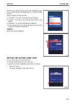
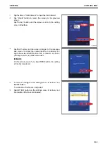
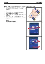
Lower the bucket edge to the ground at an arbitrary place,
tap “Measure Point” button or tap “Select” button to select
any point, and display the Point Coordinates.
2.
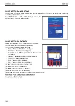
Tap the item of “Grade” of “Main-fall (A->B)”, and input the
numeric value.
REMARK
• Set “Direction”, “Grade” of “Cross-fall”, and “Grid inter-
val” as needed.
• “A” button and “B” button are not used.
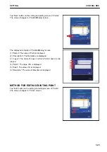
3.
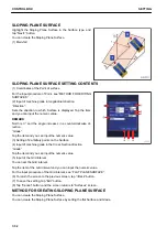
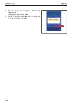
Tap “Exit” button, and the screen changes to “Message-
Box” screen.
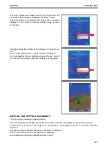
4.
To reflect the created Surface to currently setting Surface,
tap ENTER button.
REMARK
On this screen, even if you tap ENTER button, the setting
will not be completed.
SETTING
CONTROL BOX
7-33
Summary of Contents for A31001
Page 12: ...LOCATION OF SAFETY LABELS Options are shown with marks in the figure SAFETY LABELS SAFETY 2 4...
Page 106: ......
Page 107: ...SPECIFICATIONS 5 1...
Page 110: ......
Page 116: ......
Page 117: ...SETTING 7 1...
Page 311: ...EXECUTIONS 8 1...
Page 376: ...PC360LCi 11 PC390LCi 11 HYDRAULIC EXCAVATOR Form No CEAM032703...


