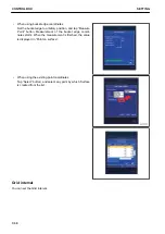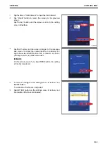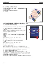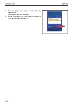
CROWN ROAD SURFACE SETTING CONTENTS
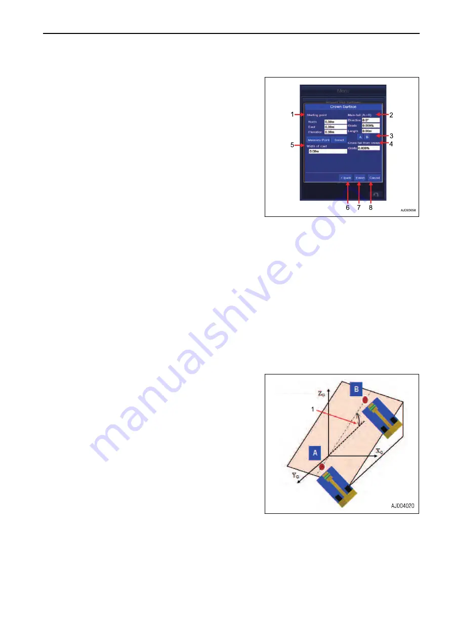
(1) Setting of “Starting point”
For the input procedure of Point, see “FLAT PLANE SUR-
FACE”.
(2) Input of machine grade in longitudinal direction
“Direction”:
Sets the direction to which Surface is displayed. Tap the item
and you can input the numeric value.
REMARK
North is 0 ° and the angle increases in a counterclockwise di-
rection.
“Grade”:
Tap the item and you can input the numeric value.
(3) Setting of 2 arbitrary points on Crown road surface
(4) Input of machine grade in cross-fall direction on crown road
“Grade”:
Tap the item and you can input the numeric value.
(5) Input of “Width of road”
You can set the width of the road.
Tap the item of “Width of road”, and you can input the numeric value.
(6) To return the screen to the previous screen, tap “<Back” button.
(7) To save the setting, tap “Exit” button.
(8) Tap “Cancel” button, and the screen returns to the editing screen of “Surfaces”.
METHOD FOR CREATING CROWN ROAD SURFACE
You can create the Crown road surface.
Set the starting point.
1.
Lower the bucket edge to the ground at an arbitrary place,
tap “Measure Point” button or tap “Select” button to select
any point, and display the Point Coordinates.
(1) Main-fall
2.
Measure the Coordinates of 2 points on the existing slope.
Lower the bucket edge on “A” position, and tap “A” button.
3.
Measurement is started and the Coordinates of “A” is dis-
played.
4.
Move the bucket edge to “B” position.
5.
Set the bucket edge at “B” position, and tap “B” button.
6.
Measurement is started and the Coordinates of “B” is dis-
played.
7.
Tap the item of “Length” and input the overall length of the
road.
8.
Tap the item of “Width of road”, and input the width of road.
9.
Tap “Exit” button, and the screen changes to “MessageBox” screen.
To reflect the created Surface to currently setting Surface, tap ENTER button. Not to reflect it to currently
setting Surface, tap RETURN button.
REMARK
On this screen, even if you tap ENTER button, the setting will not be completed.
SETTING
CONTROL BOX
7-37
Summary of Contents for A31001
Page 12: ...LOCATION OF SAFETY LABELS Options are shown with marks in the figure SAFETY LABELS SAFETY 2 4...
Page 106: ......
Page 107: ...SPECIFICATIONS 5 1...
Page 110: ......
Page 116: ......
Page 117: ...SETTING 7 1...
Page 311: ...EXECUTIONS 8 1...
Page 376: ...PC360LCi 11 PC390LCi 11 HYDRAULIC EXCAVATOR Form No CEAM032703...


