• Perpendicular against the horizontal plane
In this setting, the constant vertical distance against Sur-
face is measured.
REMARK
In the Travel mode, this setting is automatically selected.
• Perpendicular against Surface
In this setting, the constant perpendicular distance against
Surface is measured.
REMARK
In the Semi-auto mode, this setting is automatically select-
ed.
STEERING REFERENCES SETTINGS
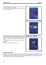
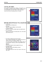
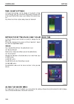
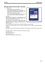
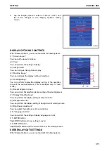
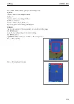
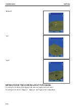
The setting for the bucket tooth position to be steering to the selected alignment data can be set.
Tap the “Steer Indication” button on the “Guidance Set-
tings”screen.
The display changes to the “Steer Indication” screen.
CONTROL BOX
SETTING
7-62
Summary of Contents for A31001
Page 12: ...LOCATION OF SAFETY LABELS Options are shown with marks in the figure SAFETY LABELS SAFETY 2 4...
Page 106: ......
Page 107: ...SPECIFICATIONS 5 1...
Page 110: ......
Page 116: ......
Page 117: ...SETTING 7 1...
Page 311: ...EXECUTIONS 8 1...
Page 376: ...PC360LCi 11 PC390LCi 11 HYDRAULIC EXCAVATOR Form No CEAM032703...


