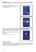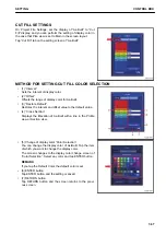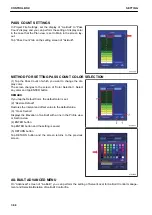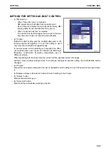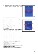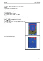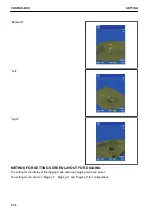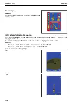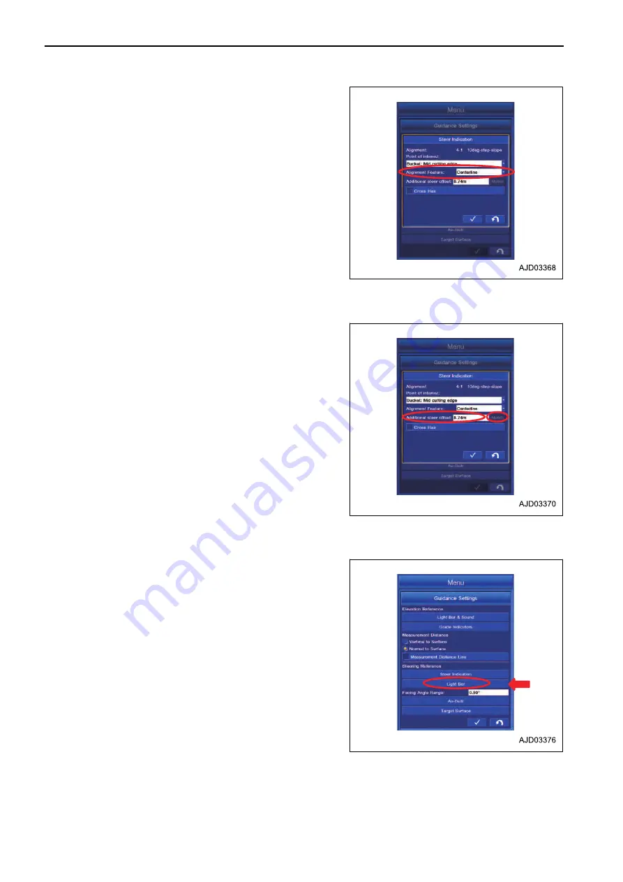
Tap the “Point of interest:” column for selecting the position of
the alignment data.
You can select the following position for the alignment data.
• “Shoulder-left” The left side of the alignment data)
• “Centerline” The center of the alignment data)
• “Shoulder-right” The right side of the alignment data)
ADDITIONAL STEER OFFSET IN STEER INDICATION SETTINGS
Alignment data for steering can be offset.
The numeric value can be changed in the column of the steer-
ing function as shown below.
• “Shoulder-left” The width from the left end of the alignment
data to the inside is “inc)”.
• “Centerline” The width from the center to the right side is
“increased (+)”.
• “Shoulder-right” The width from the right end of the align-
ment data to the inside is “decreased(-)”.
Tap the “Match” button for offsetting alignment data to the
bucket tooth position. The offset amount is automatically set.
METHOD FOR SETTING LIGHT BAR IN STEERING REFERENCES
The setting of the light bar displayed for steering can be set.
Tap the “Light Bar” button on the “Guidance Settings” screen.
CONTROL BOX
SETTING
7-64
Summary of Contents for A31001
Page 12: ...LOCATION OF SAFETY LABELS Options are shown with marks in the figure SAFETY LABELS SAFETY 2 4...
Page 106: ......
Page 107: ...SPECIFICATIONS 5 1...
Page 110: ......
Page 116: ......
Page 117: ...SETTING 7 1...
Page 311: ...EXECUTIONS 8 1...
Page 376: ...PC360LCi 11 PC390LCi 11 HYDRAULIC EXCAVATOR Form No CEAM032703...


