1.
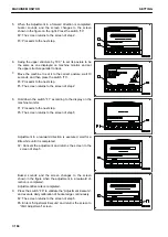
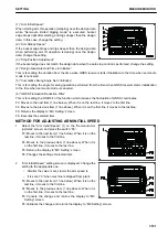
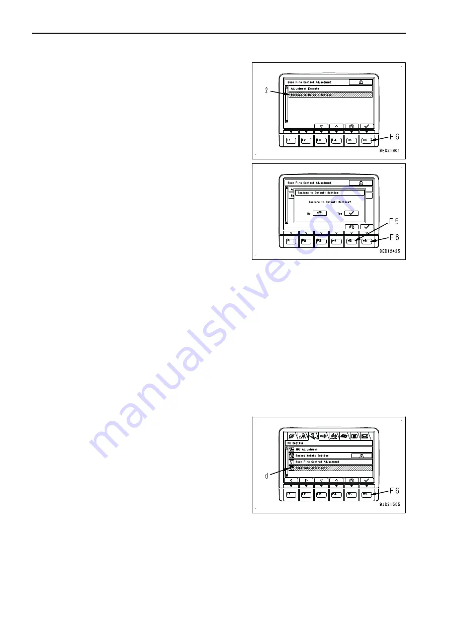
Select the “Restore to Default Setting” (2) on the “Boom
Fine Control Adjustment”screen, and press the switch
“F6”.
F3: Moves to the next item (1 line below). When it is on the
last line, it moves to the first line.
F4: Moves to the previous item (1 line above). When it is
on the first line, it moves to the last line.
F5: Returns the display to “MC Setting” screen.
F6: Executes the selected item.
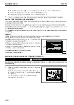
2.
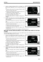
Confirmation screen is displayed. Hold down the switch
“F6” to restore to default setting.
F5: Returns the display to “Boom Fine Control Adjustment”
screen without restoring the value to the default setting..
F6: Returns the display to “Boom Fine Control Adjustment”
screen restoring the value to the default setting.
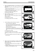
SEMI-AUTO ADJUSTMENT
Each item of this menu is for detail setting related to “Semi-auto limited digging mode”.
REMARK
• Setting change of this item cannot be performed while “Semi-auto limited digging mode” is enabled.
Change the mode to the manual mode, and perform the setting.
• Auto grade assist is the control to raise the boom automatically so that the bucket edge does not dig deeper
than the design data when arm is operated near the design data.
• Auto stop control is the control to decelerate or stop the work equipment automatically so that the bucket
edge does not dig deeper than the design data when the arm is not operated and the boom or bucket is
operated near the design data.
• When GNSS communication state is not good, GNSS receiver becomes initializing state and error is dis-
played on the screen of control box. This state is called Initializing. Normally, the state becomes initializing
is completed state.
For details, see “IF Initializing IS DISPLAYED (3-72)”.
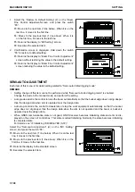
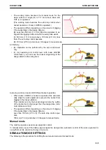
Select the “Semi-auto Adjustment” (d) on the “MC Setting”
screen, and press the switch “F6”.
F3: Moves to the next item (1 line below). When it is on the last
line, it moves to the first line.
F4: Moves to the previous item (1 line above). When it is on the
first line, it moves to the last line.
F5: Returns the display to the standard screen.
F6: Executes the selected item.
MACHINE MONITOR
SETTING
7-190
Summary of Contents for A31001
Page 12: ...LOCATION OF SAFETY LABELS Options are shown with marks in the figure SAFETY LABELS SAFETY 2 4...
Page 106: ......
Page 107: ...SPECIFICATIONS 5 1...
Page 110: ......
Page 116: ......
Page 117: ...SETTING 7 1...
Page 311: ...EXECUTIONS 8 1...
Page 376: ...PC360LCi 11 PC390LCi 11 HYDRAULIC EXCAVATOR Form No CEAM032703...


