1.
The machine may behave unexpectedly if the bucket edge
selection is not proper.
For the setting of bucket edge, see “METHOD FOR SET-
TING ROUGH DIGGING SCREEN (8-15)”.
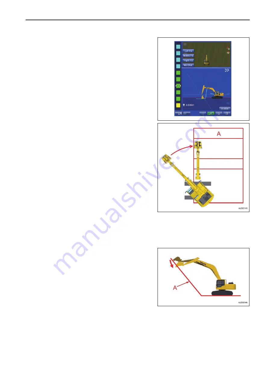
2.
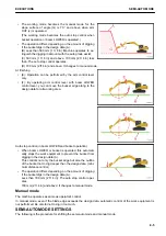
When the work equipment is moved from the place out of
the design data to the place of the design data
(For example: Operation of swing and boom lowering is
performed simultaneously)
• The work equipment decelerates sharply or stops sud-
denly at any height of position and creates the shock
after the bucket enters the design data (A).
• The machine digs too much with bucket edge or buck-
et bottom face after the bucket enters the design data
(A).
3.
The machine may dig too much with bucket edge or buck-
et bottom face in the design data when the machine rocks
largely on the rough ground, but it is not a trouble.
Operate the work equipment lever slowly for accurate fin-
ishing.
Stop position adjustment function is provided in order to
adjust the digging amount of the auto stop control. For details, see “SEMI-AUTO ADJUSTMENT (7-190)”.
Semi-auto mode changes to manual mode when the digging amount is 700 mm {2 ft 4 in} and above.
Create the design surface 700 mm {2 ft 4 in} and above away from that pipe when there is a buried pipe
such as water pipe, or gas pipe, or high-voltage pipe in the jobsite so that the operation will be easy as risk
to damage the buried pipe is lowered.
4.
The machine may dig too much in the design data (A) with
bucket edge or bucket bottom face if you start digging from
the place near the MAX reach.
$-'
EXECUTIONS
SEMI-AUTO MODE
8-3
Summary of Contents for A31001
Page 12: ...LOCATION OF SAFETY LABELS Options are shown with marks in the figure SAFETY LABELS SAFETY 2 4...
Page 106: ......
Page 107: ...SPECIFICATIONS 5 1...
Page 110: ......
Page 116: ......
Page 117: ...SETTING 7 1...
Page 311: ...EXECUTIONS 8 1...
Page 376: ...PC360LCi 11 PC390LCi 11 HYDRAULIC EXCAVATOR Form No CEAM032703...


