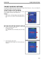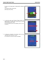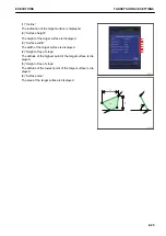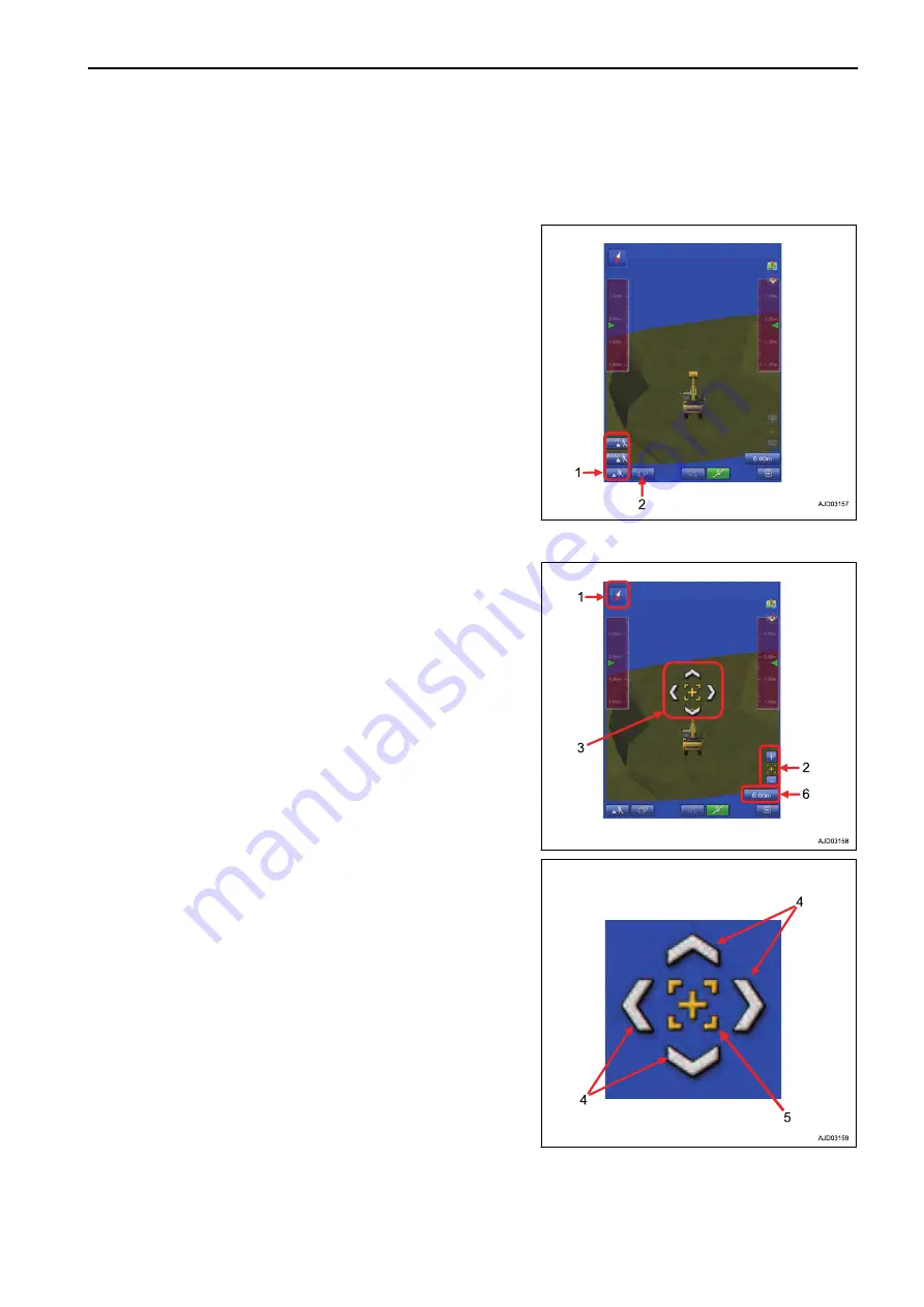
TRAVEL MODE
Use the Travel mode when machine travels in the job site.
TRAVEL MODE SETTINGS
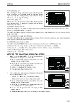
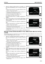
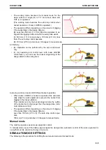
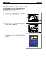
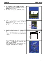
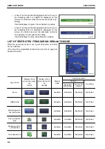
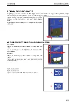
Tap the button (1) at bottom left of the working screen, and but-
ton pops up. Tap the button (1) and select Travel mode.
Tap the button (2) to switch the display between the screen set
in “Driving1” and the screen set in “Driving2”.
REMARK
Semi-auto mode cannot be used when the travel mode is se-
lected.
DISPLAY OF TRAVEL MODE
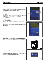
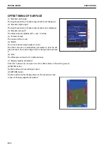
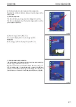
(1) Azimuth angle compass
It shows the direction. Red arrow direction is north.
(2) Zoom in, zoom out key
Zoom in or zoom out the screen by tapping this key.
Tap the center (5) of scroll key, and the view returns to the de-
fault position.
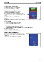
(3) Scroll key
Tap the machine while the 3D view is displayed, and the scroll
key is displayed.
Tap the outside part (4) of scroll key, and the display area
scrolls.
Tap the center (5) of scroll key, and the view returns to the de-
fault position.
Tap the any position other than the scroll key to set the scroll
key to Non-display.
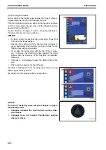
(6) Design data offset
Tap this button, and the design data offset menu (Adjust eleva-
tion menu) pops up.
The design data can be offset vertically (up and down) by in-
putting the value in the design data offset menu.
EXECUTIONS
TRAVEL MODE
8-11
Summary of Contents for A31001
Page 12: ...LOCATION OF SAFETY LABELS Options are shown with marks in the figure SAFETY LABELS SAFETY 2 4...
Page 106: ......
Page 107: ...SPECIFICATIONS 5 1...
Page 110: ......
Page 116: ......
Page 117: ...SETTING 7 1...
Page 311: ...EXECUTIONS 8 1...
Page 376: ...PC360LCi 11 PC390LCi 11 HYDRAULIC EXCAVATOR Form No CEAM032703...

