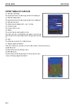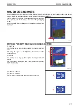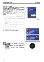
(10) Cross section line of the design data
Cross section line of the design data is displayed.
Cross section line is displayed in pink full line.
(11) Cross section line of the target surface
Cross section line of the target surface is displayed.
Cross section line is displayed in green full line.
(12) Extended line of cross section line of the target surface
Extended line of cross section line of the target surface is dis-
played.
Extended line is displayed in green broken line.
REMARK
Use this line as a guideline for digging the current construction
surface.
(13) Workable range
The working range of work equipment is displayed.
For details, see “GUIDANCE SETTINGS (7-53)”.
REMARK
• This is displayed only when travel mode is selected.
• The working range of work equipment depends on the inclination angle of machine.
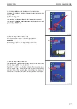
(14) Display of abnormality
Error message is displayed on the screen.
For details, see “TROUBLES AND ACTIONS (3-72)”.
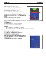
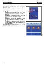
TEMPORARY DESIGN MENU
When the designed data (the design data) is not displayed, the
design data offset button changes to
t
emporary design surface
creation button.
Tap this button, and “Temp. Design” menu pops up.
$-'
EXECUTIONS
TRAVEL MODE
8-13
Summary of Contents for A31001
Page 12: ...LOCATION OF SAFETY LABELS Options are shown with marks in the figure SAFETY LABELS SAFETY 2 4...
Page 106: ......
Page 107: ...SPECIFICATIONS 5 1...
Page 110: ......
Page 116: ......
Page 117: ...SETTING 7 1...
Page 311: ...EXECUTIONS 8 1...
Page 376: ...PC360LCi 11 PC390LCi 11 HYDRAULIC EXCAVATOR Form No CEAM032703...

