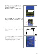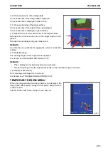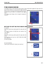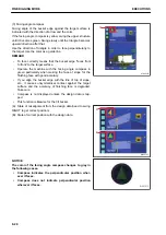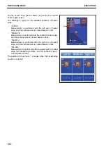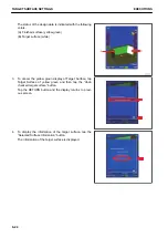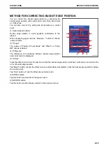
METHOD FOR CREATING TEMPORARY DESIGN SURFACE
You can create the design surface such as flat surface and
slope, etc. temporarily.
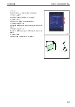
(1) “Controlled Grade”
Input the grade of the design surface you are going to create.
(2) “Point”
Select the reference point at the measurement of bucket edge
position. (left end, middle, right end)
(3) “North”, “East”, “Elevation”
Input the coordinates of control point of the design surface you
are going to create.
You can also measure the bucket edge position.
(4) “Elevation adjustment”
Input the offset amount of the control point in vertical direction.
(5) “Grid interval”
Input the grid interval to display.
(6) “Measure pt...”
Measure the current bucket edge position.
Result of measurement for bucket edge position is used for creating the design surface.
(7) “Select”
Point coordinates data which has already been measured are used for creating the design surface.
(8) “A”, “B” button
These are used when you measure the bucket edge position of 2 points of A and B, and create the inclined
surface which passes those 2 points.
TARGET SURFACE SETTINGS
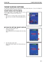
METHOD FOR SETTING TARGET SURFACE
Target surface can be set by tapping the design data (A) or the
section line (pink line) on sectional view.
The design data is highlighted when it is set.
METHOD FOR RESETTING TARGET SURFACE
Tap any place other than the design data to cancel the target surface setting.
TRAVEL MODE
EXECUTIONS
8-14
Summary of Contents for A31001
Page 12: ...LOCATION OF SAFETY LABELS Options are shown with marks in the figure SAFETY LABELS SAFETY 2 4...
Page 106: ......
Page 107: ...SPECIFICATIONS 5 1...
Page 110: ......
Page 116: ......
Page 117: ...SETTING 7 1...
Page 311: ...EXECUTIONS 8 1...
Page 376: ...PC360LCi 11 PC390LCi 11 HYDRAULIC EXCAVATOR Form No CEAM032703...


