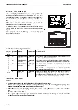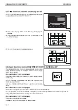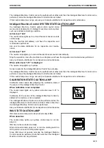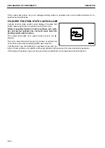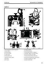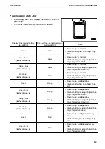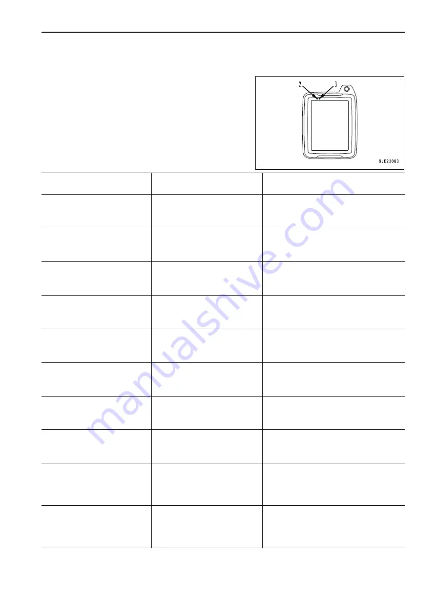
Power supply state LED
• Power supply state LED displays the state of control box
power supply.
• Control box power is supplied from GNSS receiver.
Display of the internal battery
state LED (2)
Display of the external power sup-
ply state LED (3)
State
Green
Green
•
Power supply is normal.
•
Internal battery has been fully charg-
ed.
Green, blue
(flashes alternately)
Green
•
Power supply is normal.
•
Internal battery is being charged (bat-
tery charged level: high).
Orange, blue
(flashes alternately)
Green
•
Power supply is normal.
•
Internal battery is being charged (bat-
tery charged level: medium).
Red, blue
(flashes alternately)
Green
•
Power supply is normal.
•
Internal battery is being charged (bat-
tery charged level: low).
Green
Orange
•
Power supply voltage is low.
•
Internal battery has been fully charg-
ed.
Green, blue
(flashes alternately)
Orange
•
Power supply voltage is low.
•
Internal battery is being charged (bat-
tery charged level: high).
Orange, blue
(flashes alternately)
Orange
•
Power supply voltage is low.
•
Internal battery is being charged (bat-
tery charged level: medium).
Red, blue
(flashes alternately)
Orange
•
Power supply voltage is low.
•
Internal battery is being charged (bat-
tery charged level: low).
Green
Red
•
Power supply voltage is extremely
low.
•
Internal battery has been fully charg-
ed.
Green, blue
(flashes alternately)
Red
•
Power supply voltage is extremely
low.
•
Internal battery is being charged (bat-
tery charged level: high).
OPERATION
EXPLANATION OF COMPONENTS
3-21
Summary of Contents for A31001
Page 12: ...LOCATION OF SAFETY LABELS Options are shown with marks in the figure SAFETY LABELS SAFETY 2 4...
Page 106: ......
Page 107: ...SPECIFICATIONS 5 1...
Page 110: ......
Page 116: ......
Page 117: ...SETTING 7 1...
Page 311: ...EXECUTIONS 8 1...
Page 376: ...PC360LCi 11 PC390LCi 11 HYDRAULIC EXCAVATOR Form No CEAM032703...


