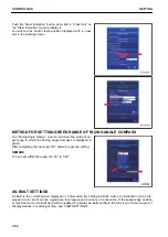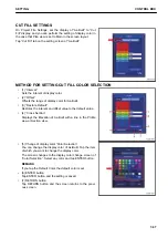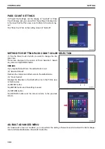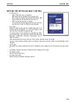
2.
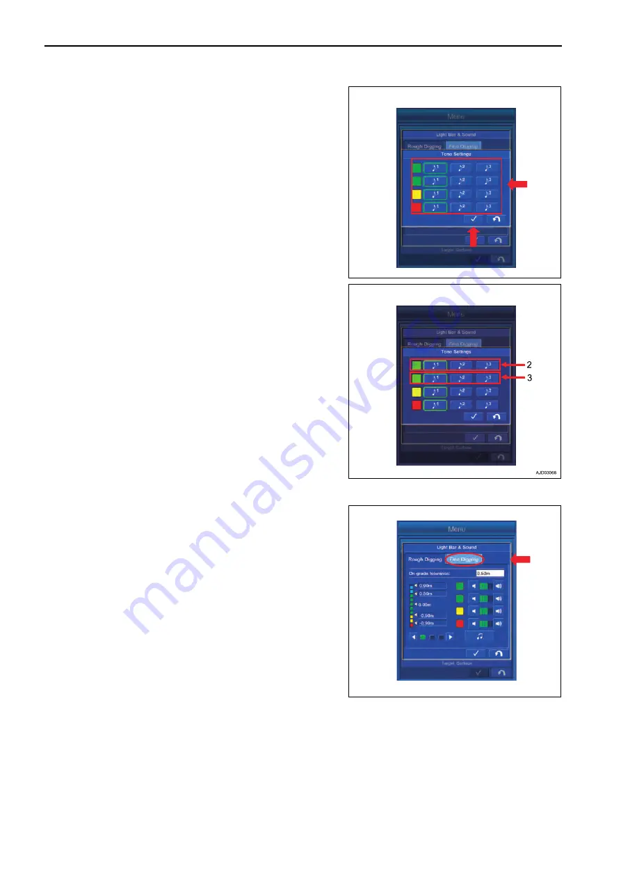
Select and tap any Tone for each color of Light Bar on
“Tone Settings” screen.
After completing the selection, tap ENTER button to save
the setting.
3.
There are 2 green tolerances of Light Bar, and the Sound
can be set separately for the position of bucket edge either
above Surface or below Surface.
(2): The volume can be set in the case that bucket edge is
within the green range of Light Bar, and above Surface.
(3): The volume can be set in the case that bucket edge is
within the green range of Light Bar, and below Surface.
FINE DIGGING MODE SETTINGS
You can perform the setting of Light Bar & Sound in Fine Dig-
ging mode.
Select “Fine Digging” on “Light Bar & Sound” screen.
For the following 5 items, the contents are the same as those
which can be controlled in Rough Digging mode.
• The displayed contents of “Light Bar & Sound” guidance
setting screen
For this item, see “LIGHT BAR AND SOUND SETTING
CONTENTS”.
• Setting of allowable value in Rough Digging mode
For this item, see “METHOD FOR SETTING TOLERANCE
IN ROUGH DIGGING MODE”.
• Changing Light Bar display range in Rough Digging mode
For this item, see “METHOD FOR CHANGING LIGHT
BAR DISPLAY RANGE IN ROUGH DIGGING MODE”.
• Setting volume of Sound
For this item, see “METHOD FOR SETTING SOUND VOLUME”.
• Setting tone of Sound
For this item, see “METHOD FOR SETTING SOUND TONE”.
GRADE INDICATORS SETTINGS
You can perform the setting of Grade Indicator.
CONTROL BOX
SETTING
7-58
Summary of Contents for A31001
Page 12: ...LOCATION OF SAFETY LABELS Options are shown with marks in the figure SAFETY LABELS SAFETY 2 4...
Page 106: ......
Page 107: ...SPECIFICATIONS 5 1...
Page 110: ......
Page 116: ......
Page 117: ...SETTING 7 1...
Page 311: ...EXECUTIONS 8 1...
Page 376: ...PC360LCi 11 PC390LCi 11 HYDRAULIC EXCAVATOR Form No CEAM032703...


