MACHINE MONITOR
MC SETTING
There is MC setting menu in the user menu on machine monitor, and it performs various settings related to
“Semi-auto limited digging mode”.
For the user menu other than “MC Setting” menu, see the Operation and Maintenance Manual of standard ma-
chine.
For “Semi-auto limited digging mode”, see “SEMI-AUTO MODE (8-2)”.
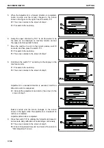
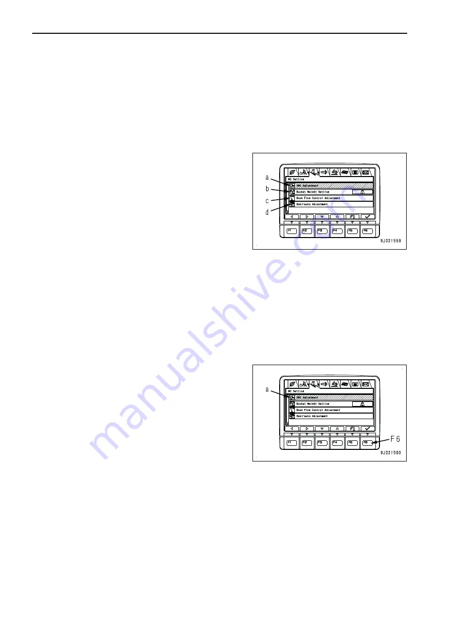
Each item of this menu is for setting related to “Semi-auto limit-
ed digging mode”.
This menu is for setting and confirming the following items.
(a): “IMU Adjustment”
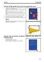
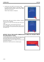
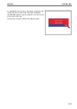
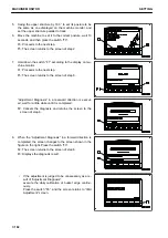
(b): “Bucket Weight Setting” (*)
(c): “Boom Fine Control Adjustment” (*)
(d): “Semi-auto Adjustment” (*)
(*): Setting change of this item cannot be performed in “Semi-
auto limited digging mode”. Change the mode to the manual
mode.
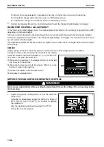
The following operations can be performed with switches F1 to F6 on the user menu screen.
F1: Moves the selection to the left menu. When it is on the left end menu, it moves to the right end menu.
F2: Moves to the right menu. When on the right end menu, it moves to the left end menu.
F3: Moves to the next item (1 line below). When it is on the last line, it moves to the first line.
F4: Moves to the previous item (1 line above). When it is on the first line, it moves to the last line.
F5: Returns the display to the standard screen.
F6: Displays the setting screen for selected item.
IMU ADJUSTMENT
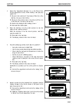
Select the “IMU Adjustment” (a) on the “MC Setting” screen,
and press the switch F6.
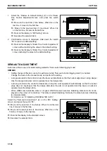
When executing the daily calibration, diagnose the necessity of
adjustment on “Adjustment Diagnosis” menu of “IMU Adjust-
ment”. If it is judged to be necessary, perform the adjustment
on “Adjustment Execute” menu.
REMARK
Setting change of this item cannot be performed during waiting
or operating of “Semi-auto limited digging mode”.
Change the mode to the manual mode, and perform the set-
ting.
F3: Moves to the next item (1 line below). When it is on the last line, it moves to the first line.
F4: Moves to the previous item (1 line above). When it is on the first line, it moves to the last line.
F5: Returns the display to the standard screen.
F6: Executes the selected item.
MACHINE MONITOR
SETTING
7-180
Summary of Contents for A31001
Page 12: ...LOCATION OF SAFETY LABELS Options are shown with marks in the figure SAFETY LABELS SAFETY 2 4...
Page 106: ......
Page 107: ...SPECIFICATIONS 5 1...
Page 110: ......
Page 116: ......
Page 117: ...SETTING 7 1...
Page 311: ...EXECUTIONS 8 1...
Page 376: ...PC360LCi 11 PC390LCi 11 HYDRAULIC EXCAVATOR Form No CEAM032703...


