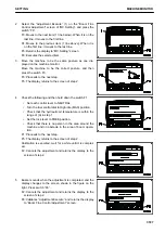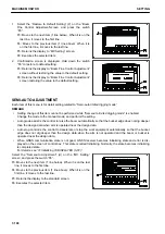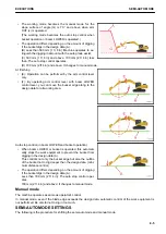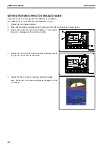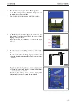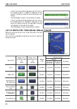
METHOD FOR ADJUSTING ARM STEADY SPEED
1.
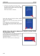
Select the “Arm Steady Speed” (2) on the “Semi-auto Ad-
justment” screen, and press the switch “F6”.
F3: Moves to the next item (1 line below). When it is on the
last line, it moves to the first line.
F4: Moves to the previous item (1 line above). When it is
on the first line, it moves to the last line.
F5: Returns the display to “MC Setting” screen.
F6: Changes the setting of selected item.
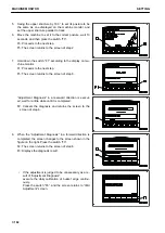
2.
“Arm Steady Speed” setting screen is displayed. Change
the setting to the appropriate one.
• Smaller the value is set, slower the arm speed is.
• It is set at “0” when machine is shipped from plant.
F3: Moves to the next item (1 line below). When it is on the
last line, it moves to the first line.
F4: Moves to the previous item (1 line above). When it is
on the first line, it moves to the last line.
F5: Cancels the change and returns the display to “MC
Setting” screen.
F6: Validates the change and returns the display to “MC Setting” screen.
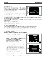
METHOD FOR ADJUSTING STOP POSITION
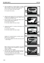
1.
Select the “Stop Position Adjustment” (3) on the “Semi-au-
to Adjustment” screen, and press the switch “F6”.
F3: Moves to the next item (1 line below). When it is on the
last line, it moves to the first line.
F4: Moves to the previous item (1 line above). When it is
on the first line, it moves to the last line.
F5: Returns the display to “MC Setting” screen.
F6: Changes the setting of selected item.
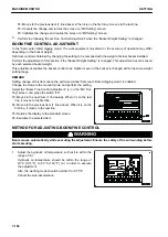
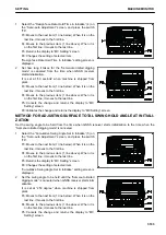
2.
“Stop Position Adjustment” setting screen is displayed.
Change it to the appropriate setting.
• If the bucket edge digs into the design data, set the
value larger.
• If bucket edge does not reach the design data, set the
value smaller.
F3: Moves to the next item (1 line below). When it is on the
last line, it moves to the first line.
F4: Moves to the previous item (1 line above). When it is
on the first line, it moves to the last line.
F5: Cancels the change and returns the display to “MC Setting” screen.
F6: Validates the change and returns the display to “MC Setting” screen.
METHOD FOR ADJUSTING SURFACE HOLD TIME AT INITIALIZATION
Set how long it takes for the “Semi-auto limited digging mode” to be canceled from the time when GNSS receiv-
er starts initialization.
MACHINE MONITOR
SETTING
7-192
Summary of Contents for A31001
Page 12: ...LOCATION OF SAFETY LABELS Options are shown with marks in the figure SAFETY LABELS SAFETY 2 4...
Page 106: ......
Page 107: ...SPECIFICATIONS 5 1...
Page 110: ......
Page 116: ......
Page 117: ...SETTING 7 1...
Page 311: ...EXECUTIONS 8 1...
Page 376: ...PC360LCi 11 PC390LCi 11 HYDRAULIC EXCAVATOR Form No CEAM032703...

