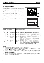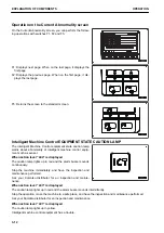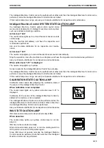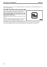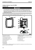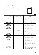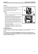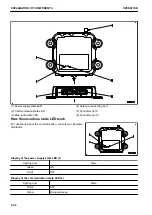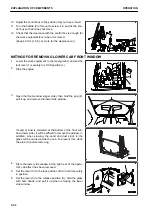
(b) Manual mode
Pressing this switch during the semi-auto mode changes the
mode to the manual mode.
The symbol indicating the manual mode is displayed on the
control box, and voice signal sounds.
Shifting from the semi-auto mode to the manual mode can be
performed regardless of the machine condition.
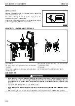
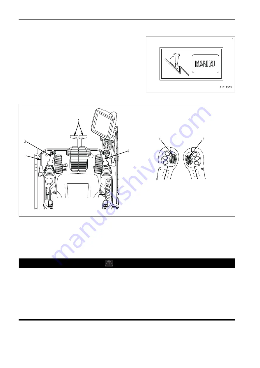
CONTROL LEVERS AND PEDALS
9JD29751
(1) Lock lever
(2) Travel levers (with pedal and auto-deceleration
system)
(3) L.H. work equipment control lever (with auto-decel-
eration system)
(4) R.H. work equipment control lever (with auto-de-
celeration system)
(5) Not used
(6) 1st Attachment Proportional Control Switch
LOCK LEVER
k
k
WARNING
• When opening/closing the window, adjusting the position of operator's seat, and leaving the opera-
tor's seat, set the lock lever securely to LOCK position. If the lock lever is not at LOCK position and
the control levers or control pedals are touched by mistake, it may lead to serious personal injury
or death.
• Always check that the lock lever is in LOCK position.
• When pulling up or pushing down the lock lever, be careful not to touch the work equipment control
lever.
• Before raising the lock lever, make sure that all levers and pedals are set to NEUTRAL position.
EXPLANATION OF COMPONENTS
OPERATION
3-18
Summary of Contents for A31001
Page 12: ...LOCATION OF SAFETY LABELS Options are shown with marks in the figure SAFETY LABELS SAFETY 2 4...
Page 106: ......
Page 107: ...SPECIFICATIONS 5 1...
Page 110: ......
Page 116: ......
Page 117: ...SETTING 7 1...
Page 311: ...EXECUTIONS 8 1...
Page 376: ...PC360LCi 11 PC390LCi 11 HYDRAULIC EXCAVATOR Form No CEAM032703...


