


FOREWORD
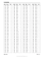
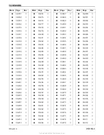
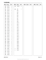
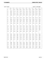
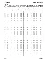
STANDARD TIGHTENING TORQUE
WB156-5
00-13
2
12
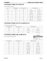
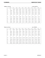
TIGHTENING TORQUE OF HOSE NUTS
00
Use these torques for hose nuts.
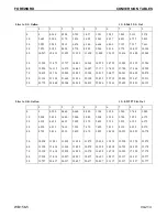
TIGHTENING TORQUE OF SPLIT FLANGE BOLTS
00
Use these torques for split flange bolts.
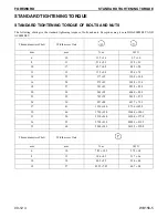
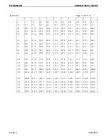
TIGHTENING TORQUE FOR FLARED NUTS
00
Use these torques for flared part of nut.
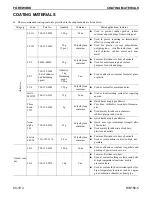
Nominal No.
Thread diameter
Width across flats
Tightening torque
mm
mm
N·m
lbf ft
02
14
19
24.5 ±4.9
18.1 ±3.6
03
18
24
49 ±19.6
36.1 ±14.4
04
22
27
78.5 ±19.6
57.9 ±14.4
05
24
32
137.3 ±29.4
101.3 ±21.7
06
30
36
176.5 ±29.4
130.2 ±21.7
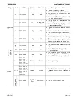
10
33
41
196.1 ±49
144.6 ±36.1
12
36
46
245.2 ±49
180.9 ±36.1
14
42
55
294.2 ±49
217.0 ±36.1
Thread diameter
Width across flats
Tightening torque
mm
mm
N·m
lbf ft
10
14
65.7 ±6.8
48.5 ±5.0
12
17
112 ±9.8
82.6 ±7.2
16
22
279 ±29
205.8 ±21.4
Thread diameter
Width across flats
Tightening torque
mm
mm
N·m
lbf ft
14
19
24.5 ±4.9
18.0 ±3.6
18
24
49 ±19.6
36.1 ±14.5
22
27
78.5 ±19.6
57.9 ±14.5
24
32
137.3 ±29.4
101.3 ±21.7
30
36
176.5 ±29.4
130.2 ±21.7
33
41
196.1 ±49
144.6 ±36.1
36
46
245.2 ±49
180.9 ±36.1
42
55
294.2 ±49
217.0 ±36.1
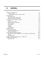
Summary of Contents for A63001
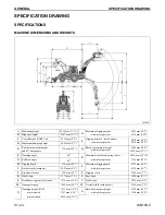
Page 33: ...GENERAL BACKHOE ARM WB156 5 01 3 2 BACKHOE ARM STANDARD ARM...
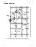
Page 34: ...GENERAL BACKHOE ARM 01 4 2 WB156 5 TELESCOPIC ARM RETRACTED...
Page 35: ...GENERAL BACKHOE ARM WB156 5 01 5 2 TELESCOPIC ARM EXTENDED...
Page 41: ...This as a preview PDF file from best manuals com Download full PDF manual at best manuals com...


