background image

GENERAL

MACHINE SYSTEMS SPECIFICATIONS

01-6 

1

WB156PS-5

MACHINE SYSTEMS SPECIFICATIONS

ENGINE

Model  . . . . . . . . . . . . . . . . . . . . . . . . . . . . . . . . . . . . . . . . . . . . . . . . . . . . . . . . . . . . . . . . . . . . . . . . . . . .  Komatsu S4D102LE-2
Type . . . . . . . . . . . . . . . . . . . . . . . . . . . . . . . . . . . . . . . . . . . . . . . . . . . . . . . . . . . . . . Vertical, 4-cycle water-cooler diesel engine
Aspiration  . . . . . . . . . . . . . . . . . . . . . . . . . . . . . . . . . . . . . . . . . . . . . . . . . . . . . . . . . . . . . . . . . . . . . . . . . . . . . . . . .Turbocharged
Number of cylinders . . . . . . . . . . . . . . . . . . . . . . . . . . . . . . . . . . . . . . . . . . . . . . . . . . . . . . . . . . . . . . . . . . . . . . . . . . . . . . . . . .  4
Bore x stroke   . . . . . . . . . . . . . . . . . . . . . . . . . . . . . . . . . . . . . . . . . . . . . . . . . . . . . . . . . . . . . . . .  114 x 135 mm (4.49 x 5.31 in)

Piston displacement. . . . . . . . . . . . . . . . . . . . . . . . . . . . . . . . . . . . . . . . . . . . . . . . . . . . . . . . . . . . . . . . . . . . . . . . .  4.5 

l

 (275 in

3

)

Compression ratio . . . . . . . . . . . . . . . . . . . . . . . . . . . . . . . . . . . . . . . . . . . . . . . . . . . . . . . . . . . . . . . . . . . . . . . . . . . . . . . . . . 18:1
Horsepower rating:

Gross horsepower rating @ 2200 rpm . . . . . . . . . . . . . . . . . . . . . . . . . . . . . . . . . . . . . . . . . . . . . . . . . . . . . .  73.8 kW 99 HP
Net horsepower (SAE J 1349) . . . . . . . . . . . . . . . . . . . . . . . . . . . . . . . . . . . . . . . . . . . . . . . . . . . . . . . . . . . .  70.8 kW 95 HP
Max. torque @ 1500 rpm . . . . . . . . . . . . . . . . . . . . . . . . . . . . . . . . . . . . . . . . . . . . . . . . . . . . . . . . . . . .  414 N·m (305 lbf ft)

Fuel system . . . . . . . . . . . . . . . . . . . . . . . . . . . . . . . . . . . . . . . . . . . . . . . . . . . . . . . . . . . . . . . . . . . . . . . . . . . . . . Direct injection
Air cleaner . . . . . . . . . . . . . . . . . . . . . . . . . . . . . . . . . . .  Dry-type with double elements and dust evacuator, condition indicator
Lubrication system:

Method . . . . . . . . . . . . . . . . . . . . . . . . . . . . . . . . . . . . . . . . . . . . . . . . . . . . . . . . . . . . . . . . . . .  Gear pump, force-lubrication
Filter . . . . . . . . . . . . . . . . . . . . . . . . . . . . . . . . . . . . . . . . . . . . . . . . . . . . . . . . . . . . . . . . . . . . . . . . . . . . . . . . . . . . . Full-flow

Cooling system  . . . . . . . . . . . . . . . . . . . . . . . . . . . . . . . . . . . . . . . . . . . . . . . . . . . . . . . . . . . . . . . . Radiator water cooled system
Starting system  . . . . . . . . . . . . . . . . . . . . . . . . . . . . . . . . . . . . . . . . .Electric motor with air pre-heating system for cold climate

ELECTRICAL SYSTEM

Voltage. . . . . . . . . . . . . . . . . . . . . . . . . . . . . . . . . . . . . . . . . . . . . . . . . . . . . . . . . . . . . . . . . . . . . . . . . . . . . . . . . . . . . . . . . . . 12 V
Battery . . . . . . . . . . . . . . . . . . . . . . . . . . . . . . . . . . . . . . . . . . . . . . . . . . . . . . . . . . . . . . . . . . . . . . . . . . . . . . .  100 Ah (860 CCA)
Alternator  . . . . . . . . . . . . . . . . . . . . . . . . . . . . . . . . . . . . . . . . . . . . . . . . . . . . . . . . . . . . . . . . . . . . . . . . . . . . . . . . . . . . . . . . 95 A
Starter motor . . . . . . . . . . . . . . . . . . . . . . . . . . . . . . . . . . . . . . . . . . . . . . . . . . . . . . . . . . . . . . . . . . . . . . . . . . . . . . . . . . . . 3.2 kW

SERVICE REFILL CAPACITIES

Engine oil  . . . . . . . . . . . . . . . . . . . . . . . . . . . . . . . . . . . . . . . . . . . . . . . . . . . . . . . . . . . . . . . . . . . . . . . . . . . . . . . . . .  9

 l

 (2.4 gal)

Cooling system  . . . . . . . . . . . . . . . . . . . . . . . . . . . . . . . . . . . . . . . . . . . . . . . . . . . . . . . . . . . . . . . . . . . . . . . . . . . . .  14 

l

 (3.7 gal)

Fuel tank  . . . . . . . . . . . . . . . . . . . . . . . . . . . . . . . . . . . . . . . . . . . . . . . . . . . . . . . . . . . . . . . . . . . . . . . . . . . . . . . .  150 

l

 (39.6 gal)

Hydraulic tank . . . . . . . . . . . . . . . . . . . . . . . . . . . . . . . . . . . . . . . . . . . . . . . . . . . . . . . . . . . . . . . . . . . . . . . . . . . . .  41 

l

 (10.8 gal)

Hydraulic system capacities  . . . . . . . . . . . . . . . . . . . . . . . . . . . . . . . . . . . . . . . . . . . . . . . . . . . . . . . . . . . . . . . . . .  97 

l

 (25.6 gal)

Front axle oil . . . . . . . . . . . . . . . . . . . . . . . . . . . . . . . . . . . . . . . . . . . . . . . . . . . . . . . . . . . . . . . . . . . . . . . . . . . . . . . 7.5 

l

 (2.0 gal)

Rear axle oil  . . . . . . . . . . . . . . . . . . . . . . . . . . . . . . . . . . . . . . . . . . . . . . . . . . . . . . . . . . . . . . . . . . . . . . . . . . . . . . 14.5 

l

 (3.8 gal)

Gearbox oil, Power Shuttle . . . . . . . . . . . . . . . . . . . . . . . . . . . . . . . . . . . . . . . . . . . . . . . . . . . . . . . . . . . . . . . . . . . 20.2 

l

 (5.3 gal)

Gearbox oil, Power Shift . . . . . . . . . . . . . . . . . . . . . . . . . . . . . . . . . . . . . . . . . . . . . . . . . . . . . . . . . . . . . . . . . . . . . 28.0 

l

 (7.4 gal)

Summary of Contents for A73001

Page 1: ...ca Corp It is our policy to improve our products whenever it is possible and practical to do so We reserve the right to make changes or add improvements at any time without incurring any obligation to...

Page 2: ...WB156PS 5 12 CONTENTS 00 01 GENERAL 01 1 10 STRUCTURE FUNCTION AND MAINTENANCE STANDARD 10 1 20 TESTING ADJUSTING AND TROUBLESHOOTING 20 1 30 DISASSEMBLY AND ASSEMBLY 30 1 90 OTHER 90 1 Find manuals a...

Page 3: ...b 01 2 b 01 3 b 01 4 b 01 5 b 01 6 b 01 7 b 01 8 b 01 9 b 01 10 b 01 11 b 01 12 b 01 13 b 01 14 b 01 15 b 01 16 b 10 1 b 10 2 b 10 3 b 10 4 b 10 5 b 10 6 b 10 7 b 10 8 b 10 9 b 10 10 b Mark Page Rev...

Page 4: ...b 20 25 b 20 26 b 20 27 b 20 28 b 20 29 b 20 30 b 20 31 b 20 32 b 20 33 b Mark Page Rev 20 34 b 20 35 b 20 36 b 20 37 b 20 38 b 20 39 b 20 40 b 20 41 b 20 42 b 20 43 b 20 44 b 20 45 b 20 46 b 20 47 b...

Page 5: ...97 b 30 98 b 30 99 b 30 100 b 30 101 b 30 102 b Mark Page Rev 30 103 b 30 104 b 30 105 b 30 106 b 30 107 b 30 108 b 30 109 b 30 110 b 30 111 b 30 112 b 30 113 b 30 114 b 30 115 b 30 116 b 30 117 b 30...

Page 6: ...30 226 b 30 227 b 30 228 b 30 229 b 30 230 b 30 231 b 30 232 b 30 233 b 30 234 b Mark Page Rev 30 235 b 30 236 b 30 237 b 30 238 b 30 239 b 30 240 b 30 241 b 30 242 b 30 243 b 30 244 b 30 245 b 30 246...

Page 7: ...0 327 b 30 328 b 30 329 b 30 330 b 30 331 b 30 332 b 30 333 b Mark Page Rev 30 334 b 30 335 b 30 336 b 30 337 b 30 338 b 30 339 b 30 340 b 30 341 b 30 342 b 30 343 b 30 344 b 30 345 b 30 346 b 30 347...

Page 8: ...FOREWORD 00 2 6 b WB156PS 5 Mark Page Rev Mark Page Rev Mark Page Rev Mark Page Rev Find manuals at https best manuals com...

Page 9: ...work equipment to the ground If this is not possi ble insert the safety pin or use blocks to prevent the work equipment from falling In addition be sure to lock all the control levers and hang warning...

Page 10: ...ll not be damaged by contact with other parts when the machine is being operated 10 When installing high pressure hoses be sure that they are not twisted Damaged tubing is dangerous Be extremely caref...

Page 11: ...E FUNCTION AND MAINTENANCE STANDARD This section gives the judgement standards when inspecting disassembled parts It explains the structure and function of each component It serves not only to give an...

Page 12: ...mber for each item 3 Additional pages Additional pages are indicated by a hyphen and numbered after the page number File as in the example Example REVISED EDITION MARK 00 When a manual is revised an e...

Page 13: ...subjected to each rope will increase with the hanging angles The table below shows the variation of allowable load when hoisting with two ropes each of which is allowed to sling up to 1000 kg 2205 lb...

Page 14: ...es of the hole and shaft The tightness of fit is decided by the tolerance Indication of size of rotating shaft and hole and relationship drawing of them 2 Standard clearance and standard value The cle...

Page 15: ...wable value it must be checked or repaired The permissible value is estimated from various tests or experiences in most cases however it must be judged after considering the operating condition and cu...

Page 16: ...250 g Polyethylene container Used as sealant for machined holes Holtz MH 705 790 126 9120 75 g Tube Used as heat resisting sealant for repairing engine Three bond 1735 179 129 9140 2 g Polyethylene c...

Page 17: ...g type Used as sealant for flywheel housing intake manifold oil pan thermostat housing etc Three bond 1211 790 129 9090 100 g Tube Used as heat resisting sealant for repairing engines Molybdenum disul...

Page 18: ...3 2 1 4 9 7 1 0 8 13 31 4 2 9 23 2 2 1 10 17 65 7 6 8 48 5 5 0 12 19 112 9 8 82 6 7 2 14 22 177 19 130 5 14 0 16 24 279 29 205 8 23 4 18 27 383 39 282 5 28 8 20 30 549 58 404 9 42 8 22 32 745 78 549 5...

Page 19: ...6 36 1 14 4 04 22 27 78 5 19 6 57 9 14 4 05 24 32 137 3 29 4 101 3 21 7 06 30 36 176 5 29 4 130 2 21 7 10 33 41 196 1 49 144 6 36 1 12 36 46 245 2 49 180 9 36 1 14 42 55 294 2 49 217 0 36 1 Thread dia...

Page 20: ...m mm Range Target 08 08 14 5 88 8 82 4 33 6 50 7 35 5 42 10 10 17 9 8 12 74 7 22 9 39 11 27 8 31 12 12 19 14 7 19 6 10 84 14 45 17 64 13 01 14 14 22 19 6 24 5 14 45 18 07 22 54 16 62 16 16 24 24 5 34...

Page 21: ...l etc 5 65 0 32 5 23 4 6 37 Charging and signal 15 84 0 45 13 36 7 0 59 Starting Glow plug 40 85 0 80 42 73 11 4 135 Starting 60 127 0 80 63 84 13 6 178 Starting 100 217 0 80 109 1 17 6 230 Starting P...

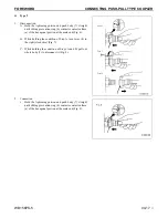
Page 22: ...ld hose adapter 1 or hose 5 and insert it in mating adapter 3 aligning them with each other Fig 4 Do not hold rubber cap portion 4 B After inserting the hose in the mating adapter perfectly pull it ba...

Page 23: ...a of the hexagonal portion at the male end Fig 6 B While holding the condition of Step A turn lever 8 to the right clockwise Fig 7 C While holding the condition of Steps A and B pull out whole body 7...

Page 24: ...at the male end Fig 10 B While holding the condition of Step A push cover 10 straight until it contacts surface b of the hexagonal por tion at the male end Fig 11 C While holding the condition of Step...

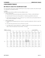
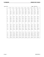
Page 25: ...n the table so divide by 10 move the decimal one place to the left to convert it to 55 mm B Carry out the same procedure as above to convert 55 mm to 2 165 inches C The original value 550 mm was divid...

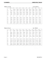
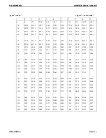
Page 26: ...68 3 307 3 346 3 386 3 425 3 465 3 504 90 3 543 3 583 3 622 3 661 3 701 3 740 3 780 3 819 3 858 3 898 Kilogram to Pound 1 kg 2 2046 lb 0 1 2 3 4 5 6 7 8 9 0 0 2 20 4 41 6 61 8 82 11 02 13 23 15 43 17...

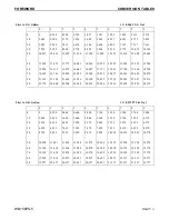
Page 27: ...1 662 21 926 22 190 22 455 22 719 22 983 23 247 23 511 90 23 775 24 040 24 304 24 568 24 832 25 096 25 361 25 625 25 889 26 153 Liter to U K Gallon 1 l 0 21997 U K Gal 0 1 2 3 4 5 6 7 8 9 0 0 0 220 0...

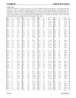
Page 28: ...00 3 607 6 614 8 622 0 629 3 636 5 643 7 90 651 0 658 2 665 4 672 7 679 9 687 1 694 4 701 6 708 8 716 1 100 723 3 730 5 737 8 745 0 752 2 759 5 766 7 773 9 781 2 788 4 110 795 6 802 9 810 1 817 3 824...

Page 29: ...1294 1309 1323 1337 1351 1365 1380 1394 1408 100 1422 1437 1451 1465 1479 1493 1508 1522 1536 1550 110 1565 1579 1593 1607 1621 1636 1650 1664 1678 1693 120 1707 1721 1735 1749 1764 1778 1792 1806 18...

Page 30: ...9 66 2 12 2 54 129 2 31 7 89 192 2 26 1 15 5 0 6 7 20 68 0 12 8 55 131 0 32 2 90 194 0 25 6 14 6 8 6 1 21 69 8 13 3 56 132 8 32 8 91 195 8 25 0 13 8 6 5 6 22 71 6 13 9 57 134 6 33 3 92 197 6 24 4 12 1...

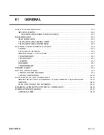
Page 31: ...YSTEM 01 6 SERVICE REFILL CAPACITIES 01 6 TRANSMISSION 01 7 TOTAL MASS 01 7 LOADER 01 7 BACKHOE 01 7 TIRE PRESSURE 01 7 WEIGHT TABLE 01 8 LIFTING THE MACHINE 01 9 LIFTING POSITION MARKS 01 9 LIFTING P...

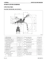
Page 32: ...arm 3046 mm 10 0 4239 mm 13 11 F Dumping angle 45o R Maximum reach from swing center 6034 mm 19 10 G Rollback angle 45o with telescopic arm 7164 mm 23 6 H Digging depth 138 mm 5 4 S Maximum digging de...

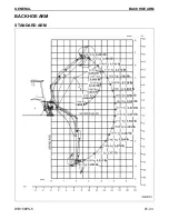
Page 33: ...GENERAL BACKHOE ARM WB156PS 5 01 3 1 BACKHOE ARM STANDARD ARM...

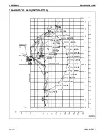
Page 34: ...GENERAL BACKHOE ARM 01 4 1 WB156PS 5 TELESCOPIC ARM RETRACTED...

Page 35: ...GENERAL BACKHOE ARM WB156PS 5 01 5 1 TELESCOPIC ARM EXTENDED...

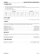
Page 36: ...ction Air cleaner Dry type with double elements and dust evacuator condition indicator Lubrication system Method Gear pump force lubrication Filter Full flow Cooling system Radiator water cooled syste...

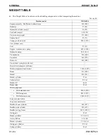
Page 37: ...een dramatically reduced Standard bucket width 2 356 mm 7 ft 9 in Standard bucket capacity SAE 0 95 m3 1 25 yd3 Standard bucket weight 454 kg 1 000 lb Lifting capacity at maximum height 3 900 kg 8 598...

Page 38: ...ic pump 36 8 81 1 Transmission 254 560 Front axle 262 578 Rear axle 430 948 Front wheel complete with rim Rear wheel complete with rim Work equipment front loader 1 100 2 425 Boom 313 690 Bucket 436 9...

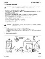
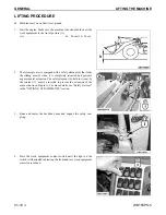
Page 39: ...m to prevent accidental extension Engage the backhoe boom safety coupling Press the work equipment control switch to the LOCK position Insert the backhoe lock pin to lock the backhoe arm in position C...

Page 40: ...iding arm 2 when it is completely retracted and prevents any accidental extension The safety element 6 held in its seat by the retainer 7 must be inserted to prevent the extension of the arm as shown...

Page 41: ...This as a preview PDF file from best manuals com Download full PDF manual at best manuals com...

Reviews:

Related manuals for A73001