background image

OPERATION

EXPLANATION OF COMPONENTS

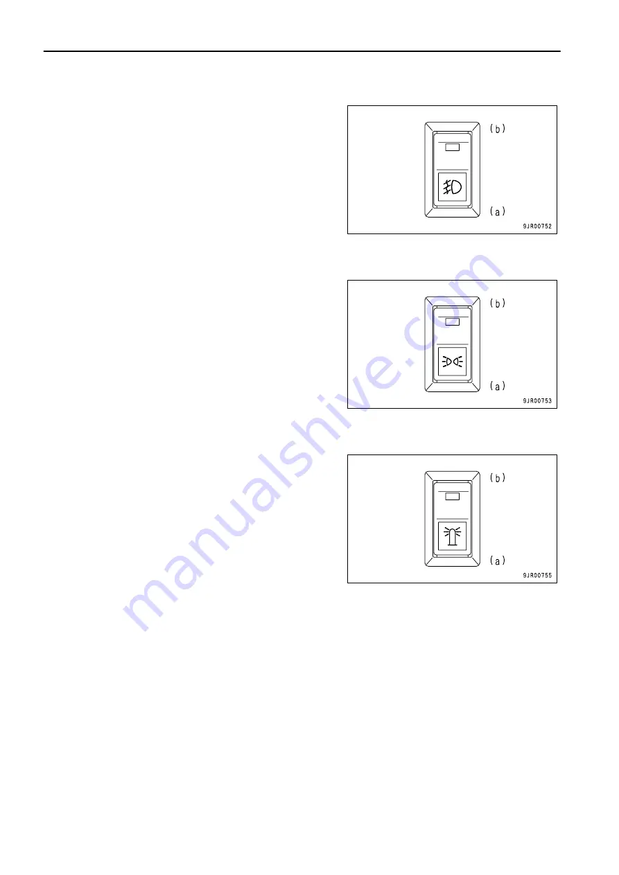
FOG LAMP SWITCH

(If equipped)
This switch (11) is used to switch on the fog lamp.

(a): Fog lamp goes out
(b): Fog lamp lights up

When working at night, the symbol inside the switch lights up
regardless of the selected position of the switch.

SIDE LAMP SWITCH

(If equipped)
This switch (12) is used to switch on the side lamp.

(a): Side lamp goes out
(b): Side lamp lights up
When working at night, the symbol inside the switch lights up
regardless of the selected position of the switch.

YELLOW ROTATING LAMP SWITCH

(If equipped)
This switch (13) is used to switch the yellow rotating lamp on and
off. When the lamp is switched on, it lights up and rotates.

(a): Yellow rotating lamp goes out
(b): Yellow rotating lamp lights up

When working at night, the symbol inside the switch lights up
regardless of the selected position of the switch.

3 - 36

Summary of Contents for Galeo HD405-7R

Page 1: ......

Page 2: ... 1 1 ...

Page 3: ... so that all relevant personnel can read it at any time Storage location for the Operation and Maintenance Manual On inside of left door If this manual is lost or damaged contact your distributor immediately to arrange for its replacement For details regardingthe machine serial No you will need to provide your Komatsu distributor see TABLE TO ENTER SERIAL NO AND DISTRIBUTOR PAGE 1 6 This manual us...

Page 4: ...personal injury or death Follow the instructions in the safety message This signal word indicates an imminently hazardous situation which if not avoided will result in death or serious injury This signal word indicates a potentially hazardous situation which if not avoided could result in death or serious injury This signal word indicates a potentially hazardous situation exists which if not avoid...

Page 5: ...t right are determined according to the view from the operator s seat in the direction of travel front of the machine A B C FRONT REAR LEFT D E RIGHT OPERATOR S SEAT VISIBILITY FROM OPERATOR S SEAT This machine complies with the visibility standard ISO 5006 This machine maintains a close visibility of a height of 1 5 m at a point 1 m away from the outside surface of the machine and a visibility fo...

Page 6: ...ng service or ordering replacement parts please inform your Komatsu distributor of the following items PRODUCT IDENTIFICATION NUMBER PIN MACHINE SERIAL NO PLATE It is located on the left front end of the frame The design of the nameplate differs according to the territory ENGINE SERIAL NO PLATE On the top of the engine cylinder head cover 1 5 ...

Page 7: ...AND DISTRIBUTOR SERVICE METER POSITION It is at the center bottom of the machine monitor TABLE TO ENTER SERIAL NO AND DISTRIBUTOR Machine serial No Engine serial No Product identification number PIN Distributor name Address Service Personnel Phone Fax 1 6 ...

Page 8: ...ION 2 13 PRECAUTIONS WHEN GETTING ON OR OFF MACHINE 2 14 DO NOT GET CAUGHT IN DUMP BODY 2 16 PRECAUTIONS RELATED TO PROTECTIVE STRUCTURES 2 16 UNAUTHORIZED MODIFICATION 2 16 PRECAUTIONS RELATED TO ATTACHMENTS AND OPTIONS 2 17 PRECAUTIONS WHEN RUNNING ENGINE INSIDE BUILDING 2 17 PRECAUTIONS FOR OPERATION 2 18 PRECAUTIONS FOR JOBSITE 2 18 STARTING ENGINE 2 20 OPERATION 2 22 TRANSPORTATION 2 26 TOWIN...

Page 9: ...INING TRAVEL ROAD 3 117 TRANSPORTATION 3 118 PRECAUTIONS WHEN TRANSPORTING 3 118 STEPS FOR TRANSPORTATION 3 118 METHOD OF SECURING MACHINE 3 118 METHOD OF LIFTING MACHINE 3 119 COLD WEATHER OPERATION 3 122 PRECAUTIONS FOR LOW TEMPERATURE 3 122 PRECAUTIONS AFTER COMPLETION OF WORK 3 123 AFTER COLD WEATHER 3 124 LONG TERM STORAGE 3 125 BEFORE STORAGE 3 125 DURING STORAGE 3 125 AFTER STORAGE 3 125 PR...

Page 10: ... SERVICE 4 82 EVERY 8000 HOURS SERVICE 4 84 EVERY 15000 HOURS SERVICE 4 85 SPECIFICATIONS 5 1 SPECIFICATIONS 5 2 ATTACHMENTS OPTIONS 6 1 SELECTING DUMP BODY 6 2 HANDLING AIR SUSPENSION SEAT 6 3 SEAT ADJUSTMENT 6 3 REMOVAL AND INSTALLATION OF HEADREST 6 5 HANDLING AUTOMATIC SPIN REGULATOR ASR 6 6 EXPLANATION OF COMPONENTS 6 6 ACTUATION OF ASR SYSTEM 6 7 PRECAUTIONS WHEN USING 6 7 BLEEDING AIR FROM ...

Page 11: ...L 6 66 EXPLANATION OF COMPONENTS 6 67 METHOD OF OPERATION 6 70 USE OF REAR VIEW MONITOR 6 73 NAME AND FUNCTON OF EACH PART OF REAR VIEW MONITOR 6 73 SETTING OF REAR VIEW MONITOR 6 76 CAUTIONS WHEN USING REAR VIEW MONITOR 6 76 HANDLING DUMPING COUNTER 6 77 HANDLING MACHINES EQUIPPED WITH KOMTRAX 6 78 BASIC PRECAUTIONS 6 78 INDEX 7 1 1 10 ...

Page 12: ... 2 1 ...

Page 13: ...ENT 2 12 PROVIDE FIRE EXTINGUISHER AND FIRST AID KIT 2 12 IF ANY PROBLEM IS FOUND 2 12 FIRE PREVENTION 2 13 ACTION IF FIRE OCCURS 2 13 PRECAUTIONS TO PREVENT FIRE 2 13 PRECAUTIONS WHEN GETTING ON OR OFF MACHINE 2 14 USE HANDRAILS AND STEPS WHEN GETTING ON OR OFF MACHINE 2 14 NO JUMPING ON OR OFF MACHINE 2 14 NO PEOPLE ON DUMP BODY 2 14 PRECAUTIONS WHEN STANDING UP FROM OPERATOR S SEAT 2 15 PRECAUT...

Page 14: ...EFORE STARTING ENGINE 2 20 PRECAUTIONS WHEN STARTING ENGINE 2 21 PRECAUTIONS IN COLD AREAS 2 21 STARTING WITH BOOSTER CABLES 2 21 OPERATION 2 22 CHECKS BEFORE OPERATION 2 22 PRECAUTIONS WHEN TRAVELING IN FORWARD OR REVERSE 2 22 PRECAUTIONS WHEN TRAVELING 2 23 TRAVELING ON SLOPES 2 23 PRECAUTIONS WHEN OPERATING 2 23 PRECAUTIONS WHEN LOADING DUMP BODY 2 24 PRECAUTIONS WHEN OPERATING DUMP BODY 2 24 T...

Page 15: ...ECAUTIONS WHEN WORKING UNDER MACHINE 2 31 PROPER TOOLS 2 31 PRECAUTIONS FOR INSPECTION AND MAINTENANCE 2 32 PRECAUTIONS WHEN WELDING 2 32 HANDLING BATTERY 2 32 PRECAUTIONS WHEN USING HAMMER 2 33 PRECAUTIONS WITH HIGH TEMPERATURE COOLANT 2 33 PRECAUTIONS WITH HIGH TEMPERATURE OIL 2 33 PRECAUTIONS WITH HIGH PRESSURE OIL 2 34 PRECAUTIONS WITH HIGH PRESSURE FUEL 2 34 HANDLING HIGH PRESSURE HOSES AND P...

Page 16: ...e correct place and always keep them clean When cleaning them do not use organic solvents or gasoline These may cause the labels to peel off There are also other labels in addition to the warning signs and safety labels Handle those labels in the same way If the labels are damaged lost or cannot be read properly replace them with new ones For details of the part numbers for the labels see this man...

Page 17: ... SAFETY SAFETY LABELS POSITION FOR ATTACHING SAFETY LABELS 2 6 ...

Page 18: ... SAFETY LABELS 1 Precaution about modifying ROPS 09620 B2000 2 Caution for rotation of engine fan fan belt 09667 A0880 3 Caution for opening radiator cap 09653 A0641 4 Caution for opening hydraulic tank cap 09653 A0641 2 7 ...

Page 19: ... SAFETY SAFETY LABELS SAFETY SAFETY LABELS 5 Warning for handling suspension 09659 A0881 6 Warnings for electric wire Warnings for crush hazard when inspection and maintenance 569 93 82450 2 8 ...

Page 20: ... SAFETY SAFETY LABELS 7 Caution before starting Caution when traveling in reverse 569 93 81720 8 Caution when handling battery cable 09808 A1681 9 Exhaust pipe is hot 09817 A1103 2 9 ...

Page 21: ...g falling down 09805 C0881 11 Precautions for handling accumulator 09659 A057B 12 Caution when gandling battery This safety label is provided by the battery manufacturer 13 Jump start prohibited 09842 A0481 This safety label is fixed to the engine starting motor 2 10 ...

Page 22: ...l thoroughly If there are any places in this manual that you do not understand ask the person in charge of safety to give an explanation PREPARATIONS FOR SAFE OPERATION PRECAUTIONS REGARDING SAFETY RELATED EQUIPMENT Be sure that all guards covers and mirrors are in their proper position Have guards and covers repaired immediately if they are damaged Understand the method of use of safety features ...

Page 23: ...y obstruct operation and cause the machine to move unexpectedly resulting in serious personal injury or death Do not stick suction pads to the window glass Suction pads act as a lens and may cause fire Do not use a cell phone when driving or operating the machine This may lead to mistakes in operation which could cause serious personal injury or death Never bring any dangerous objects such as flam...

Page 24: ...nger that they may catch fire Do not weld or use a cutting torch to cut any pipes or tubes that contain flammable liquids Determine well ventilated areas for storing oil and fuel Keep the oil and fuel in the determined place and do not allow unauthorized persons to enter When carrying out grinding or welding work on the machine move any flammable materials to a safe place before starting Fire caus...

Page 25: ...e foot with the handrail and steps to ensure that you support yourself Before getting on or off the machine check the handrails and steps and if there is any oil grease or mud on them wipe it off immediately In addition repair any damage and tighten any loose bolts Do not grip the control levers when getting on or off the machine Never climb on the engine hood or covers where there are no non slip...

Page 26: ...njury or death PRECAUTIONS WHEN LEAVING MACHINE If the proper procedures are not taken when parking the machine the machine may suddenly move off by itself and this may lead to serious personal injury or death Always do the following When leaving the machine always lower the dump body completely lock with dump lever lock knob 1 set gear shift lever 2 to the N position set parking brake switch 3 to...

Page 27: ...protective structure and carry out operations without it If the protective structure is welded or holes are drilled in it or it is modified in any other way its strength may drop Consult your Komatsu distributor before carrying out any modifications If the protective structure is damaged or deformed by falling objects or by rolling over its strength will be reduced and it will not be able to fulfi...

Page 28: ...matsu distributor for advice When installing and using optional attachments read the instruction manual for the attachment and the general information related to attachments in this manual PRECAUTIONS WHEN RUNNING ENGINE INSIDE BUILDING The engine exhaust gas contains substances that may damage your health or even cause death Start or operate the engine in a place where there is good ventilation I...

Page 29: ... to ensure that the ground is safe and to prevent the machine from rolling over or falling DO NOT GO CLOSE TO HIGH VOLTAGE CABLES Do not travel or operate the machine near electric cables There is a hazard of electric shock which may cause serious personal injury or death On jobsites where the machine may go close to electric cables always do as follows Before starting work near electric cables in...

Page 30: ...ameras clean off any dirt from the lens and make sure that the camera gives a clear view CHECKING SIGNS AND SIGNALMAN S SIGNALS Set up signs to inform of road shoulders and soft ground If the visibility is not good position a signalman if necessary Operators should pay careful attention to the signs and follow the instructions from the signalman Only one signalman should give signals Make sure tha...

Page 31: ...e surface of the lens of the front lamps working lamps and rear combination lamp and check that they light up correctly Check the coolant level fuel level and oil level in engine oil pan check for clogging of the air cleaner and check for damage to the electric wiring Check that there is no mud or dust accumulated around the movable parts of the accelerator pedal or brake pedal and check that the ...

Page 32: ...starting STARTING WITH BOOSTER CABLES If any mistake is made in the method of connecting the booster cables it may cause the battery to explode so always do as follows Always wear safety goggles and rubber gloves when starting the engine with booster cable When connecting a normal machine to a problem machine with booster cables always use a normal machine with the same battery voltage as the prob...

Page 33: ...l or fuel If any problem is found carry out repairs immediately PRECAUTIONS WHEN TRAVELING IN FORWARD OR REVERSE Lock the cab door and windows securely both when they are open and when they are closed If another person is allowed on the machine that person may sit only in the assistant s seat If there are any persons in the area around the machine there is danger that they may be hit or caught by ...

Page 34: ...r Komatsu distributor When travelling and particularly when travelling downhill never set the gear shift lever to the Neutral position Always keep it in a speed range when travelling If the gear shift lever is at Neutral it will be impossible to use the braking force of the engine and the steering will become heavier In addition there will be insufficient cooling oil for the retarder so there is d...

Page 35: ...particularly when dumping sticky material wet clay frozen material etc on a soft ground The stability of the machine is reduced and there is danger that it may tip over TRAVELING ON SNOW COVERED OR FROZEN SURFACES Snow covered or frozen surfaces are slippery so be extremely careful when traveling or operating the machine and do not operate the levers suddenly Even a slight slope may cause the mach...

Page 36: ...knob 1 set gear shift lever 2 to the N position set parking brake switch 3 to the PARKING position then stop the engine Always close the operator s cab door and use the key to lock all the equipment in order to prevent any unauthorized person from moving the machine Always remove the key take it with you and leave it in the specified place If it is necessary to park the machine on a slope set bloc...

Page 37: ...ing the hazard of the machine tipping over or falling so particular care is necessary Always do as follows Perform loading and unloading on firm level ground only Maintain a safe distance from the edge of the road or cliff Always use ramps of adequate strength Be sure that the ramps are wide long and thick enough to provide a safe loading slope Take suitable steps to prevent the ramps from moving ...

Page 38: ...owing see the METHOD OF TOWING MACHINE PAGE 3 129 Always confirm that the wire rope or drawbar used for towing has ample strength for the weight of the machine being towed Never use a wire rope which has cut strands A reduced diameter B or kinks C There is danger that the rope may break during the towing operation Always wear leather gloves when handling wire rope Never tow a machine on a slope Du...

Page 39: ...oolbox keep it in the pocket for the Operation and Maintenance Manual KEEP WORKPLACE CLEAN AND TIDY Do not leave hammers or other tools lying around in the work place Wipe up all grease oil or other substances that will cause you to slip Always keep the work place clean the tidy to enable you to carry out operations safely If the work place is not kept clean and tidy there is the danger that you w...

Page 40: ...rforming any inspection and maintenance Lower the dump body completely set dump lever 1 to the HOLD position lock with dump lever lock knob 2 then stop the engine Set parking brake switch 3 to the PARKING position to apply the parking brake then put blocks in front of and behind the tires to prevent the machine from moving 2 29 ...

Page 41: ...ts there is a hazard of being caught in the parts so be careful not to come close Never drop or insert tools or other objects into the fan fan belt or other rotating parts There is danger that they may contact the rotating parts and break or be sent flying Lower the dump body completely set dump lever 1 to the HOLD position lock with dump lever lock knob 2 and take steps to prevent the dump body f...

Page 42: ...o down when the dump control lever is operated and catch or cause serious injury or even death to the person carrying out the inspection Always carry out the operation to remove or insert the body pivot pin with at least two workers This operation is carried out with the dump body raised so if the dump body comes down during the operation it may lead to serious injury or even death For details see...

Page 43: ...able battery filler solution to the UPPER LEVEL mark Do not smoke or bring any flame close to the battery Hydrogen gas is generated when the battery is being charged so remove the battery from the machine take it to a well ventilated place remove the battery caps then carry out the charging After charging tighten the battery caps securely Danger from dilute sulphuric acid When the battery is being...

Page 44: ... area before using the hammer If hard metal parts such as pins or bearings are hit with a hammer there is a hazard that pieces might be scattered and cause serious personal injury or death Always wear safety glasses and gloves If the pin is hit with strong force there is a hazard that it may fly out and injure people in the surrounding area Do not allow anyone to enter the surrounding area PRECAUT...

Page 45: ...octor immediately for medical attention PRECAUTIONS WITH HIGH PRESSURE FUEL When the engine is running high pressure is generated in the engine fuel piping When carrying out inspection or maintenance of the fuel piping system stop the engine and wait for at least 30 seconds to allow the internal pressure to go down before starting the operation HANDLING HIGH PRESSURE HOSES AND PIPING If oil or fue...

Page 46: ...ng out cleaning with compressed air there is a hazard of serious personal injury caused by flying dust or particles When using compressed air to clean the filter element or radiator wear safety glasses anti dust mask gloves and other protective equipment MAINTENANCE OF AIR CONDITIONER If air conditioner refrigerant gets into your eyes it may cause loss of sight if it contacts your skin it may caus...

Page 47: ...material of these components naturally changes over time and repeated use causes deterioration wear and fatigue As a result there is a hazard that these components may fail and cause serious personal injury or death It is difficult to judge the remaining life of these components from external inspection or the feeling when operating so always replace them at the specified interval Replace or repai...

Page 48: ...ming too high measure the pressure from time to time with an air gauge while pumping up the tire If the tire pressure goes down abnormally or the rim parts do not fit the tire there is a problem with the tire or rim parts Always contact your Komatsu distributor for repairs If the rim parts are not fitted properly when the tire is being pumped up there is danger that the rim parts may fly off so se...

Page 49: ...tires in a warehouse which unauthorized persons cannot enter If the tires must be stored outside always erect a fence and put up No Entry signs Stand the tire on level ground and block it securely so that it cannot roll or fall over if any person should touch it Do not lay the tire on its side This will deform the tire and cause it to deteriorate If the tire should fall over do not attempt to stop...

Page 50: ... 3 1 ...

Page 51: ... OPERATION GENERAL VIEW GENERAL VIEW GENERAL VIEW OF MACHINE This illustration shows the HD325 7 1 2 3 Dump body Rear wheel Front wheel 4 5 Turn signal light Head lamp 3 2 ...

Page 52: ...Lamp switch Turn signal lever Dimmer switch Steering wheel Machine monitor Retarder control lever Cigarette lighter Gear shift lever 8 9 10 11 12 13 Parking brake switch Accelerator pedal Brake pedal Secondary brake pedal Dump lever lock knob Auto retarder ARSC set lever if equipped 3 3 ...

Page 53: ...if equipped Yellow rotating lamp switch if equipped Side lamp switch if equipped Machine monitor bulb check switch Night lighting dimmer switch Hazard lamp switch 9 10 11 12 13 14 15 Emergency steering switch Power mode selector switch AISS LOW switch Front brake cut off switch Auto retarder ARSC switch if equipped ASR switch if equipped ABS switch if equipped 3 4 ...

Page 54: ...The alarm buzzer sounds for 2 seconds and then stops The monitor lamp lights up for 2 seconds and then goes out for 1 second The shift indicator displays 88 for 2 seconds and then goes out for 1 second After a 3 second system check the meter starts to function The character display shows KOMATSU for 3 seconds If the lamps do not work there is probably a failure or disconnection so please contact y...

Page 55: ...bulb switch 1 and check that there is no failure in the monitor lamps In addition to the gauges that function during the system check the meter display portion is also actuated When this happens the character display shows the machine model and the software version of the machine monitor The gauges that do not function have probably failed so please contact your Komatsu distributor for inspection ...

Page 56: ...y out inspection and maintenance an action code is displayed to recommend suitable action When the time for replacing the filter or changing the oil is reached after completion of the system check with the starting switch at the ON position the maintenance monitor caution lamps flash or light up and at the same time the filter or oil to be replaced is displayed NOTICE Information regarding the fai...

Page 57: ...probably a failure in the machine so please contact your Komatsu distributor for inspection ODOMETER This meter 2 indicates the total distance traveled in kilometers Even when the starting switch is at the OFF position while the top of machine monitor mode selector switch 1 is being pressed it indicates the total distance traveled NOTICE When the starting switch is at the OFF position if the total...

Page 58: ...displayed stop the machine immediately check the failure code and contact your Komatsu distributor for repairs REMARK The top line of the character display displays E03 and the bottom line displays CHECK RIGHT NOW and CALL in turn for 3 seconds each The telephone number is displayed on the right of the CALL display If the telephone number has not been set there is a blank For details of the method...

Page 59: ...er replacing the filter or changing the oil reset the replacement interval For details see RESET METHOD FOR FILTER OIL REPLACEMENT TIME PAGE 3 27 REMARK The top line of the character display shows the name and ID number of the item needing replacement The line at the bottom shows the remaining time until replacement and the total number of times the item has been replaced After giving the display ...

Page 60: ...REFILTER CARTRIDGE PAGE 4 62 Engine oil filter CHANGE OIL IN ENGINE OIL PAN REPLACE ENGINE OIL FILTER CARTRIDGE PAGE 4 61 Engine oil CHANGE OIL IN ENGINE OIL PAN REPLACE ENGINE OIL FILTER CARTRIDGE PAGE 4 61 Transmission oil filter Pump outlet port REPLACE TRANSMISSION OIL FILTER ELEMENT PAGE 4 64 Fuel main filter REPLACE FUEL MAIN FILTER CARTRIDGE PAGE 4 67 Corrosion resistor REPLACE CORROSION RE...

Page 61: ...ly and take the necessary action 1 2 3 Seat belt caution lamp Parking brake pilot lamp Dump body pilot lamp 4 5 6 Emergency steering pilot lamp Fuel level caution lamp Maintenance caution lamp SEAT BELT CAUTION LAMP This monitor 1 lights up if the seat belt is not fastened There is danger when traveling so always fasten your seat belt 3 12 ...

Page 62: ...LOT LAMP This monitor 4 lights up when the emergency steering is actuated Machines equipped with auto emergency steering If any problem should occur in the steering oil pressure circuit when the machine is traveling the auto emergency steering is actuated and the related lamp lights up FUEL LEVEL CAUTION LAMP This monitor 5 lights up when the level of the fuel remaining in the fuel tank goes below...

Page 63: ...ntenance are displayed on the character display at the same time so carry out inspection filling or replacement Drop in engine oil level Clogged engine oil filter Clogged air cleaner Clogged transmission oil filter Drop in engine cooling water level REMARK In addition to the above if the filter or oil replacement time is displayed on the character display the lamp will flash or light up 3 14 ...

Page 64: ...oblem and the central warning lamp will light up 1 2 3 4 5 6 7 Engine water temperature caution lamp Torque converter oil temperature caution lamp Retarder oil temperature caution lamp Battery charge circuit caution lamp Steering oil temperature caution lamp Engine oil pressure caution lamp Brake oil pressure caution lamp accumulator oil pressure 8 9 10 11 12 Tilt caution lamp Machine monitor opti...

Page 65: ...place set the shift lever to the N position and run the engine under no load at a mid range speed until the lamp goes out RETARDER OIL TEMPERATURE CAUTION LAMP This monitor 3 warns the operator that the brake oil temperature has risen When it lights up E02 BRAKE OVERHEAT is displayed on the character display at the same time so stop the machine in a safe place set the shift lever to the N position...

Page 66: ...ection The lamp lights up if the engine lubricating oil pressure goes below the specified value when the engine is running If the engine is not running the lamp does not light up BRAKE OIL PRESSURE CAUTION LAMP This monitor 7 lights up to warn the operator that the brake accumulator oil pressure has dropped below the specified value The central warning lamp and alarm buzzer are not actuated when t...

Page 67: ...cter display at the same time so stop the machine immediately at a safe place then stop the engine and carry out inspection TRANSMISSION SYSTEM CAUTION LAMP This monitor 11 lights up when a problem has been detected in the system controlled by the transmission controller When it lights up E03 CHECK RIGHT NOW is displayed on the character display at the same time so stop the machine immediately at ...

Page 68: ...m pilot lamp Turn signal pilot lamp 6 7 8 9 Shift indicator Shift lever position pilot lamp Power mode pilot lamp Auto suspension mode pilot lamp if equipped ENGINE PRE HEATING PILOT LAMP This monitor 1 lights up when the electrical heater for pre heating the engine is being actuated When the starting switch is turned to the ON position in cold weather the monitor lights up It goes out after 20 to...

Page 69: ...is actuated LOCKUP PILOT LAMP This monitor 3 lights up when the torque converter lockup is engaged and the transmission is shifted to direct drive HEAD LAMP HIGH BEAM PILOT LAMP This monitor 4 lights up when the head lamps are set to high beam TURN SIGNAL PILOT LAMP This monitor 5 flashes at the same time as the turn signal lamp flashes 3 20 ...

Page 70: ...R POSITION PILOT LAMP This monitor 7 displays the position of the shift lever The letter or number for the speed range selected by the shift lever lights up POWER MODE PILOT LAMP This monitor 8 displays the power mode When the mode is selected with the power mode selector switch either High Power P or Economy E lights up 3 21 ...

Page 71: ...tics of the suspension according to the size of the load use of the brake operation of the steering and operation of the dump control Normally it is set to the soft mode when the dump truck is traveling empty and to the medium mode when it is traveling loaded When the foot brake is operated or the machine is suddenly turned or the dump control is operated the suspension mode is switched to insure ...

Page 72: ... gauge Retarder oil temperature gauge SPEEDOMETER This meter 1 indicates the travel speed of the machine ENGINE TACHOMETER This meter 2 shows the engine speed If the gauge indicator the red range during operations the alarm buzzer will sound and the central warning lamp will light up at the same time so reduce the engine speed and the machine travel speed 3 23 ...

Page 73: ... output is automatically limited TORQUE CONVERTER OIL TEMPERATURE GAUGE This meter 5 indicates the torque converter oil temperature It should be in the white range during operation If it is in the red range during operation the alarm buzzer will sound and the central warning lamp will light up E02 TC OVERHEAT is displayed on the character display so run the engine under no load at a mid range spee...

Page 74: ... When a problem has occurred in any of EMERGENCY STOP ITEM PAGE 3 15 When action code E02 or E03 is displayed on the character display If the parking brake is applied but the shift lever is not at the N position When the dump lever is not at the FLOAT position or the dump body is raised and the shift lever is not at the N position When the engine tachometer indicates the red range 3 25 ...

Page 75: ...he service meter odometer or the action code If it is giving any other display turn the starting switch OFF then turn the starting switch to the ON position and wait for the above display to be given 2 Press the of machine monitor mode selector switch 1 It displays the overall distance traveled in reverse 3 When completing the operation press of machine monitor mode selector switch 1 or turn the s...

Page 76: ...umber of times the item has been replaced on the right 4 Press or of machine monitor mode selector switch 2 and display the item to be reset 5 Press the of machine monitor mode selector switch 1 It will change to the display in the diagram on the right The top line shows Reset and Item to be reset in turn 6 When resetting the replacement time press or of machine monitor mode selector switch 2 alig...

Page 77: ...ress the of machine monitor mode selector switch 1 The presently selected language is displayed 4 Press or of machine monitor mode selector switch 2 and select the language The available languages are English Japanese German French Italian Spanish and Swedish 5 When the of machine monitor mode selector switch 1 is pressed the language is set and the screen returns to the previous screen 6 When com...

Page 78: ...played for the telephone number Input from the first digits The cursor is displayed at the input position Press or of machine monitor mode selector switch 2 and display 0 9 To leave a blank select When the input value is decided press of machine monitor mode selector switch 1 The cursor will move to the next position 5 Repeat the procedure in Step 4 until the last digit At the last digit press of ...

Page 79: ...selector switch Emergency steering switch Parking brake switch AISS LOW switch 10 11 12 13 14 15 16 17 18 19 20 Front brake cut off switch Fog lamp switch if equipped Side lamp switch if equipped Yellow rotating lamp switch if equipped Power window switch right if equipped Power window switch left Machine monitor mode selector switch 1 2 Cigarette lighter Horn button Wiper window washer switch Roo...

Page 80: ...ngine pre heating pilot lamp lights up After the pre heating is completed the engine pre heating pilot lamp goes out START position This is the position to start the engine Hold the key at this position while cranking Release the key immediately after the engine has been started The key will return to the ON position when released LAMP SWITCH This switch 2 lights up the head lamps side clearance l...

Page 81: ...n MACHINE MONITOR BULB CHECK SWITCH Turn the starting switch ON press this switch 3 and check for any blown bulbs HAZARD LAMP SWITCH This switch 4 is used to make the left and right turn signal indicators flash a OFF b Turn signal lamp and turn signal pilot lamp flash When working at night the symbol inside the switch lights up regardless of the selected position of the switch NIGHT LIGHTING DIMME...

Page 82: ...RING SWITCH This switch 7 is used to actuate the emergency steering pump When the switch is pressed the emergency pump is actuated to make it possible to operate the steering When the switch is ON the pilot lamp red inside the switch and the pilot lamp on the machine monitor light up The emergency steering pump can be used for a maximum of 90 seconds When the emergency steering is being used keep ...

Page 83: ...s in the brake circuit and the pressure in the accumulator goes down the secondary brake is automatically applied For details of the method of releasingthe secondary brake see WHEN PARKING BRAKE HAS BEEN ACTUATED IN EMERGENCY PAGE 3 132 When working at night the symbol inside the switch lights up regardless of the selected position of the switch REMARK If the engine is stopped with the parking bra...

Page 84: ...cy roads on snow or on other slippery road surfaces set the front brake cut off switch to the b position and travel slowly at a safe speed If the front brake cut off switch is set to the a position when traveling on icy road on snow or on other slippery road surfaces there is danger that the steering will be impossible to control This switch 10 can be used to switch the braking method of according...

Page 85: ... switch on the side lamp a Side lamp goes out b Side lamp lights up When working at night the symbol inside the switch lights up regardless of the selected position of the switch YELLOW ROTATING LAMP SWITCH If equipped This switch 13 is used to switch the yellow rotating lamp on and off When the lamp is switched on it lights up and rotates a Yellow rotating lamp goes out b Yellow rotating lamp lig...

Page 86: ...cause failure of the power window Switches 14 and 15 are used to open and close the window glass The switches can only be used when the starting switch is at the ON position a Glass goes down b Glass goes up When the glass reaches the top or bottom and stops release the switch MACHINE MONITOR MODE SELECTOR SWITCH 1 2 This switch 16 is used to operate the character display CIGARETTE LIGHTER This sw...

Page 87: ...ce every 4 7 seconds Position c LOW Wiper moves at low speed Position d Hi Wiper moves at high speed When the button A at the tip of the switch is pressed washer fluid is sprayed out Do not keep the button pressed for more than 10 seconds ROOM LAMP SWITCH The switch 20 is used to turn the room lamp ON and OFF Position a OFF Position b Lights up when the door opens Position c Lights up REMARK The r...

Page 88: ...NENTS CONTROL LEVERS AND PEDALS 1 2 3 4 Brake pedal Accelerator pedal Gear shift lever Dump lever 5 6 7 Retarder control lever Dump lever lock knob Secondary barke pedal BRAKE PEDAL This pedal 1 is used to apply the wheel brakes 3 39 ...

Page 89: ...ndards EN 474 6 5 1 3 if the machine travels with the dump body not completely lowered the transmission is fixed in 1st and the gear cannot be shifted R position This is used when traveling in reverse This position uses the torque converter drive The maximum travel speed in this position is 10 6 km h 6 6 MPH It is impossible to travel in reverse if the dump body is raised Lower the dump body set t...

Page 90: ...ngine will not start When the starting switch is at the ON position if the shift lever is not at the N neutral position the shift lever position pilot lamp will flash the central warning lamp will light up and the alarm buzzer will sound If the parking brake is applied or the shift lever is not at the N neutral position the central warning lamp will light up and the alarm buzzer will sound If the ...

Page 91: ...led in direction a the greater the braking force becomes When the retarder is operated the retarder pilot lamp lights up When leaving the operator s seat always apply the parking brake DUMP LEVER LOCK KNOB WARNING When carrying out inspection of the machine with the dump body raised always set the dump lever to the HOLD position lock with the dump lever lock knob then use the body pivot pin This d...

Page 92: ... Use this pedal If the service brakes cannot be applied properly for any reason such as damage to the brake pedal REMARK If the pressure in the accumulator goes down the secondary brake is automatically applied For details of the method of canceling the secondary brake see WHEN PARKING BRAKE HAS BEEN ACTUATED IN EMERGENCY PAGE 3 132 3 43 ...

Page 93: ...for the dump body and is used when carrying out inspection or maintenance with the dump body raised Raise the dump body fully insert body pivot pins 1 Always insert the body pivot pins on both sides STOWING BODY PIVOT PIN Store the body pivot pin under the rear of the dump body Insert body pivot pin 1 then insert lock pin 2 to stow the body pivot pin LOCATION OF FIRE EXTINGUISHER If equipped Fire ...

Page 94: ...ner Depending on the degree of clogging of the element red line 1 appears in the transparent portion If red line 1 indicates 7 5 kPa 30 INCHES H2O 0 076 kg cm2 1 1 PSI clean the element immediately After cleaning press top portion 2 of the indicator to return red line 1 to its original position 3 45 ...

Page 95: ...n replacing any fuse always turn the power off turn the starting switch to OFF When replacing the fuse always use a fuse of the same capacity and type FUSE CAPACITY AND CIRCUIT NAME Fuse box I No Capacity Name of circuit 1 10A Main lamp Side lamp 2 10A Turn signal lamp 3 20A Head lamp low beam 4 20A Head lamp high beam 5 20A Head lamp low beam 6 20A Head lamp high beam 7 10A Brake lamp 8 20A Backu...

Page 96: ...Retarder controller ABS controller if equipped 22 20A Hazard lamp 23 10A Emergency steering 24 10A Room lamp Radio 25 10A Machine monitor KOMTRAX if equipped Fuse box III No Capacity Name of circuit 26 20A Fog lamp if equipped 27 20A Air conditioner controller if equipped 28 20A Heater if equipped 29 20A Heater if equipped 30 20A ABS controller if equipped 31 20A Retarder controller 32 10A Transmi...

Page 97: ...arette lighter 48 20A Air conditioner if equipped 49 20A Spare 50 20A Front wiper Fuse box V No Capacity Name of circuit 51 10A Power source for emergency steering system 52 300A Power source for engine heater 53 10A Power supply for electric priming pump Precautions when adding electrical equipment CAUTION If the electrical equipment system is changed problems may occur in the machine control Do ...

Page 98: ... Volume 2 Tone control knob 3 Display 4 Clock button Displaying frequency 5 AST 6 Preset switch 7 Seek 8 Band selector switch 9 Tuning switch POWER SWITCH VOLUME When this switch 1 is turned to the right it clicks and the power is turned on If it is turned further the speaker volume is adjusted 3 49 ...

Page 99: ... frequency and the operating mode CLOCK BUTTON DISPLAYING FREQUENCY When this button 4 is pressed the display changes to the time If it is pressed again it displays the frequency AST When this button 5 is pressed the preset stations are called up in turn When the desired broadcasting station is reached press the button again to stop it If the button is kept pressed continuously for 2 seconds it is...

Page 100: ...matically searches for stations that can be received and when it receives a station it stops BAND SELECTOR SWITCH When this switch 8 BAND is pressed the band is switched between FM and MW AM The reception band and frequency are displayed on the display TUNING SWITCH When the TUNE button U of switch 9 is pressed the frequency goes up when the V button is pressed the frequency goes down If it is kep...

Page 101: ...d tone as desired 5 To turn the radio OFF turn VOL knob 1 to the left until a click is heard METHOD OF AUTOMATIC TUNING When the SEEK switch is pressed it moves up to higher frequencies and when it finds a station that can be received it stops automatically METHOD OF MANUAL TUNING When the TUNE button U is pressed the frequency goes up when the V button is pressed the frequency goes down If it is ...

Page 102: ...tched off all the preset settings are deleted Carry out the presetting operation again It is possible to preset 6 AM MW stations and 6 FM stations METHOD OF AUTOMATIC MEMORY If the AST button is pressed for 2 seconds the broadcasting stations that can be received in the area are called up in turn and the broadcasting stations are automatically saved in the preset memory AUTOMATIC SWITCHING RECEPTI...

Page 103: ...IONS FOR USE Stow the antenna when traveling in places with low overhead clearance To ensure safety always keep the sound to a level where it is possible to hear outside sounds during operation If water gets into the speaker case or radio it may lead to an unexpected failure so be careful not to get water on the equipment Do not wipe the scales or buttons with solvent such as benzene or thinner Wi...

Page 104: ...ness button 6 Time radio display selector button 7 Tape eject button 8 Cassette door 9 Fast forward rewind buttons 10 Preset buttons 11 Metal tape button 12 Manual tuning buttons 13 Seek tuning buttons 14 Band selector button A Band display B Metal tape display C FM stereo reception display D Loudness display E Tape direction display F Preset channel display G Time frequency display 3 55 ...

Page 105: ...y is memorized in the auto store REMARK The auto store function cannot be used when the channel display is flashing When the display is flashing the preset scan function is being used Preset scan If this button is pressed for less than 0 5 second while in radio reception programs from the six preset stations in the same band will be broadcast one after another for 5 seconds each starting from No 1...

Page 106: ...easily by emphasizing the low tone when the low tones are weak Push button Actuated ON Push button again Canceled OFF TIME RADIO DISPLAY SELECTOR BUTTON This button 6 is used to switch between the Radio tape display and the Time display Correcting the time Press the button to set the time display A Correcting hour Keep the DISP button pressed and press the bottom H of the TUNING button to correct ...

Page 107: ... press the button pointing in the same direction as the lighted arrow indicating the direction of play the tape will be fast forwarded if you press the button pointing in the opposite direction the tape will rewind To stop the tape lightly press the button that is not locked The fast forward or rewind operation will be canceled If the fast forward and rewind buttons are pressed at the same time th...

Page 108: ...z for FM when TUN button is pressed the frequency goes down 9 kHz for AM or 0 1 MHz for FM If the button is pressed down and held the frequency will change continuously SEEK TUNING BUTTONS These buttons 13 are used to seek tuning When the SEEK UP button is pressed the search automatically goes up when the SEEK DN button is pressed the search automatically goes down When the next station that can b...

Page 109: ...ton 1 to select MW AM FM1 or FM2 then use the manual tuning button to select the frequency of the broadcasting station 3 Press manual memory button 2 or seek tuning button 3 4 Press preset button 4 of the number to be preset for 2 seconds while the frequency display is being shown on the display The preset channel and frequency are displayed and the presetting is completed 5 Repeat Steps 2 to 4 to...

Page 110: ...IO 1 Turn the starting switch ON then turn power switch 1 ON 2 Set band selector button 2 to AM or FM 3 Select the station with the preset buttons or manual tuning button 3 4 Adjust the volume balance and tone as desired 5 When turning the radio OFF turn power switch 1 to the left until it clicks REMARK To switch to the radio when listening to a cassette press the cassette eject button to stop the...

Page 111: ...ay is pointing to the right the top side is being played if the arrow is pointing to the left the bottom side is being played When the tape reaches the end it is automatically reversed and the other side starts to play 3 When finished with the tape press the cassette eject button to eject the tape and automatically switch to the radio REVERSING TAPE When listening to the tape press both FAST FORWA...

Page 112: ... be removed easily soak the cloth with alcohol NOTICE Handling cassette tape Clean the tape head approx once a month with a commercially available head cleaning tape Do not leave the tape any place where it is exposed to direct sunlight any place that is excessively dusty or any place where there is a magnetic field Do not use 120 minute tapes The tape is thin and it easily gets caught up inside t...

Page 113: ...CH Use this switch 1 to turn the air conditioner ON OFF When the switch is turned ON the air conditioner monitor displays the setting being used when the switch was previously turned OFF FAN SWITCH With this switch 2 it is possible to adjust the air flow from the fan to 4 levels Press the switch to increase the air flow press the switch to reduce the air flow The air flow is shown in air flow bar ...

Page 114: ...before switching to the DEF mode REMARK Air also blows out from the foot vent in DEF mode RECIRC FRESH SELECTOR SWITCH Use this switch 6 to switch between recirculation of the internal air RECIRC or intake of external air FRESH When the switch is pressed the display of RECIRC FRESH selector symbol C on the air conditioner monitor changes It changes in the order RECIRC FRESH RECIRC RECIRC Only the ...

Page 115: ...ments lighted up on the bar the lower the temperature is Press the switch to raise the temperature press the switch to lower the temperature Even when the starting switch is turned OFF the settings of each mode are retained in memory However in the following cases the settings must be made again When the machine has not been used for more than seven days When the battery voltage is extremely low W...

Page 116: ...tions are continued for a long time with the air conditioner set to the lowest temperature and minimum air flow there is danger that the receiver drier may freeze If it freezes and no cold air comes out stop using the cooling and set to a higher temperature and the maximum air flow Run for a short time under these conditions then return to the cooling operation HEATING 1 Press ON OFF switch 1 to t...

Page 117: ...switch 6 to set the vents to the desired position 6 Press air conditioner switch 7 to operate the cooling REMARK If the ambient temperature is below 0 C 32 F the air conditioner cooling may not work In this case set to RECIRC and warm up the inside of the cab then turn the air conditioner switch ON to operate the cooling When defrosting if the temperature control switch is pressed to set the tempe...

Page 118: ...e the cab too low or direct the air flow directly onto your skin Be extremely careful to select the appropriate temperature When cooling is not being used off season To prevent leakage of the refrigerant from the air conditioner cooling circuit operate the air conditioner for several minutes 2 or 3 times a month during the off season If the air conditioner is left for a long time when the refriger...

Page 119: ... carry out repairs if any problem is found 2 Remove dirt from around engine battery radiator and aftercooler Check that there is no dirt or dust accumulated around the engine radiator or aftercooler Check also that there is no flammable material dry leaves twigs etc accumulated around the battery or engine muffler turbocharger or other high temperature parts of the engine Remove any dirt or flamma...

Page 120: ...ine Tighten any loose bolts When the belt has been used for a long time if any external damage or fraying of the belt can be seen or if the clamps are broken or deformed replace the seat belt 11 Inspect tires WARNING If worn or damaged tires are used they may burst and cause serious injury or death To ensure safety do not use the following tires Wear Tires with a tread grooves of less than 15 of t...

Page 121: ...olant level in this condition there is a hazard of burns Wait for the temperature to go down then turn the cap slowly to release the pressure and remove it carefully 1 Check that the cooling water in sub tank 1 is between the FULL and LOW marks 2 If the level is LOW remove cap 2 and add the engine coolant up to the FULL mark 3 If there is no coolant in the subtank add water to the radiator through...

Page 122: ...g cm2 1 1 PSI 2 If the red line indicates 7 5 kPa 30 INCHES H2O 0 076 kg cm 2 1 1 PSI clean or replace the air cleaner element immediately For details of the method of cleaning the element see CHECK CLEAN OR REPLACE AIR CLEANER PAGE 4 22 3 After checking cleaning or replacing press the top of dust indicator 1 to return the red line to its original position 3 73 ...

Page 123: ...ater REMARK If the level of the fuel inside the fuel tank is low it is impossible to drain the water when plug 3 is loosened In this case first add fuel then drain the water If it is impossible to add fuel the water can be drained by loosening plug 4 Width across flats 14 mm 0 6 in 5 When fuel starts to come out tighten plug 3 immediately Tightening torque 1 5 2 5 Nm 0 15 0 25 kgm 1 1 1 8 lbft 6 I...

Page 124: ...emove drain plug 1 and loosen drain valve 2 to drain the excess engine oil then check the engine oil level again 6 If the oil level is correct tighten the handle of the oil filler cap securely REMARK When checking the oil level after the engine has been operated wait for at least 15 minutes after stopping the engine If the machine is at an angle make it horizontal before checking The dipstick has ...

Page 125: ...uld be above G2 When checking the oil level with the engine stopped check with sight gauge G1 as a guide line and make the final check with G2 When checking the oil level with the engine stopped wait for 20 minutes after stopping the engine and check with sight gauge G1 CHECK OIL LEVEL IN STEERING AND HOIST OIL TANK ADD OIL WARNING If the oil filler cap is removed without releasing the internal pr...

Page 126: ...Check with sight gauge H If the oil level is up to the window of sight gauge H it is suitable 2 If the oil level is not up to the window of sight gauge H add oil through pil filler F CHECK FOR LEAKAGE OF OIL FROM REAR BRAKE OIL RECOVERY TANK BREATHER 1 Check that no oil is leaking to the ground from the breather Check also that no oil is leaking from overflow tube 1 of the rear brake oil recovery ...

Page 127: ... OPERATION OPERATION DRAIN WATER SEDIMENT FROM FUEL TANK Loosen valve 1 at the bottom of the fuel tank and drain the water and sediment collected at the bottom of the tank together with the fuel 3 78 ...

Page 128: ...e the tank will go down and the fuel may not flow therefore clean the breather hole from time to time To prevent air from being sucked into the engine do not let the level in the fuel tank go down too low CHECK WHEEL HUB NUTS TIGHTEN Check for loose wheel hub nuts 1 If any are found tighten them Tightening torque 1520 to 1850 Nm 155 to 189 kgm 1121 to 1367 lbft Insert a socket wrench in a pipe and...

Page 129: ...sition and then set parking brake switch at PARKING position If inspection is carried out when the body pilot lamp is lighted up and the shift indicator shows F1 there is danger that the internal parts of the transmission may be damaged Before carrying out inspection lower the dump body securely and check that the body pilot lamp has gone out then place the gear shift lever at the D position and c...

Page 130: ...arting switch to the ON position 2 Place the gear shift lever in the R position and check that the backup alarm is working CHECK ELECTRIC WIRING WARNING If the fuses frequently blow or if there are traces of short circuits in the electrical wiring locate the cause and immediately perform repairs or contact your Komatsu distributor for repairs Keep the top surface of the battery clean and check the...

Page 131: ...Pa 0 3 kg cm2 4 3 PSI of the value in the table above DRAIN WATER FROM FUEL PRE FILTER The water separator and fuel prefilter 1 are made one and composed of 2 to 4 in the lower section 1 Water and sediment on the bottom can be checked through transparent cap 2 If there is water or sediment prepare a container to receive it under drain hose 4 2 Loosen drain valve 3 to drain the water 3 If fuel star...

Page 132: ...t forward tilt back angle C Setting seat for operator s weight Turn grip 3 to adjust the strength of the suspension Adjustment range Target 50 to 120 kg 110 to 265 lb D Adjusting backrest angle Move lever 4 up and move the backrest to the front or rear When doing this keep your back pressed against the seat back If your back is not against the seat back the seat back may spring back suddenly Adjus...

Page 133: ... seat depress the brake pedal fully and adjust the seat so that your back is pressed against the backrest 2 Sit in the seat pull the right side of the belt then insert tongue 1 into buckle 2 until a click is heard 3 When removing the belt press the red button in buckle 2 to free the belt Fit the belt so that it follows your body and is not twisted ADJUST STEERING WHEEL TILT WARNING Always stop the...

Page 134: ... dump truck s image also comes into view View Range Mirror A Must be possible to see hatched portion A and part of the machine Mirror B Must be possible to see hatched portion B and part of the machine Mirror C Must be possible to see hatched portion C and part of the machine Mirror D Must be possible to see hatched portion D and part of the machine Mirror E Must be possible to see area to rear of...

Page 135: ... OPERATION OPERATION Z Ground contact point of tire used as base 3 86 ...

Page 136: ... lever at N neutral position and set the parking brake switch to the PARKING position 1 Check that parking brake switch 1 is in the PARKING position 2 Check that gear shift lever 2 is at the N position REMARK If the starting switch is turned to the ON position when the shift lever is not at the N position the shift lever position pilot lamp and central warning lamp will flash and the alarm buzzer ...

Page 137: ...N OPERATION OPERATION OPERATION 4 Check that retarder control lever 4 is at the RELEASED position 5 Check that there is no problem in the machine monitor when starting switch 5 is turned to the ON position 3 88 ...

Page 138: ...d then try to start again When starting the engine do not depress the accelerator pedal Even if the accelerator pedal is depressed just after the engine is started the engine speed is limited by the turbo protect function After the turbo protect time however the engine speed rises sharply and the turbocharger may be damaged 1 Turn the key of starting switch 1 to the ON position The preheater pilot...

Page 139: ...for the first time after the engine oil or engine oil filter is replaced continue the low idle run for at least 20 seconds to circulate the engine oil in the engine REMARK Since the turbocharger rotates at very high speed it is seized if not lubricated well To prevent this the turbo protect mechanism works for a certain time just after the engine starts depending on the engine water temperature En...

Page 140: ... necessary to idle the engine apply a load from time to time or run at a mid range speed On machines equipped with auto emergency steering if the machine is not fully warmed up the emergency steering may be actuated momentarily when the parking brake switch is set to TRAVEL or the dump control lever is operated After the engine starts do not start operating the machine immediately First carry out ...

Page 141: ...tion 2 Lower the dump body and set the dump lever to the HOLD position 3 Run the engine at low idle for about 5 minutes to cool down gradually 4 Turn the key of starting switch 1 to the OFF position to stop the engine 5 Remove the key from starting switch 1 CHECKS AFTER STOPPING ENGINE 1 Walk around the machine and check the dump body body work and undercarriage and check also for leakage of oil a...

Page 142: ...sition and that the dump body pilot lamp is out If the dump body pilot lamp is lighted up operate the dump lever to the HOLD position then operate it to the FLOAT position to cancel the dump body HOLD condition REMARK When the engine is started the dump lever is at the FLOAT position but the dump body is at HOLD 4 Depressed the brake pedal fully Then set parking brake switch 2 to the TRAVEL positi...

Page 143: ... R or F 6 Depress accelerator pedal 5 to move the machine off NOTICE If the shift lever is shifted to a position other than N when the parking brake has not been released the central warning lamp will flash and the alarm buzzer will sound If the shift lever is shifted to a position other than N when the dump lever is at a position other than FLOAT or the body is raised the central warning lamp wil...

Page 144: ...he FLOAT position then set the gear shift lever to the R position If the gear shift lever is set to the R position when the machine is traveling forward at a speed of 4 km h 2 5MPH or more the transmission is placed in Neutral until the travel speed is reduced the brake is automatically applied and the engine is also throttled NOTICE When shifting between FORWARD and REVERSE stop the machine compl...

Page 145: ...epressed for a long time the brake may overheat and its life will be shortened If the parking brake is used to stop the machine the brake will be damaged Do not use the parking brake except when stopping in emergencies or when parking the machine after stopping it NORMAL STOPPING Release accelerator pedal 1 and depress brake pedal 2 to stop the machine 3 96 ...

Page 146: ...f sufficient braking force cannot be obtained simply by operating the retarder control lever depress secondary brake pedal 2 to stop the machine The secondary brake applies the front and rear wheel brakes and the parking brake REMARK If the machine is stopped with the secondary brake the central warning lamp will flash and the alarm buzzer will sound If this happens return the gearshift lever to t...

Page 147: ...red position and the transmission will automatically shift to a position to match the travel speed Regardless of the position of the gear shift lever if the dump body is raised the speed range is set to 1st Always lower the dump body when traveling NOTICE When shifting between FORWARD and REVERSE stop the machine completely and run the engine at low idle when shifting the lever After moving the sh...

Page 148: ...down to a lower range until the travel speed goes down to the 2nd range or the brake is released Maintaining the speed range reduces the speed when shifting and this reduces the shock SKIP SHIFT For normal gearshifting the transmission shifts one gear range at a time When traveling uphill and the travel speed drops suddenly the transmission jumps one gear range when shifting down to reduce the tra...

Page 149: ...ever again 2 If the retarder still does not work even when the retarder control lever is operated again release the retarder control lever fully Then depress the brake pedal stop the machine and ask your Komatsu distributor to carry out repairs Operate the retarder gradually If it is operated suddenly there is danger that the tires may slip Do not move the gear shift lever to the N position when t...

Page 150: ...hine reduces speed the transmission will automatically shift down to the appropriate gear range If the condition of the road makes it necessary to travel downhill in 1st set the gear shift lever to any position except D 6 5 4 3 2 L 3 When traveling downhill operate retarder control lever 2 run the engine at a speed of 1800 to 2200 rpm and travel so that the retarder brake oil temperature gauge is ...

Page 151: ...ndicular line down 3 Take the point where it crosses the line for travel resistance 11 as B and draw a horizontal line 4 Take the point where it crosses the performance curve as C and draw a perpendicular line down Take the point where this line crosses the travel speed scale as D 5 The following information can be obtained from this procedure From point D Maximum permissible speed 28 km h 17 4 MP...

Page 152: ... OPERATION OPERATION HD325 HD405 3 103 ...

Page 153: ... OPERATION OPERATION Brake performance Downhill distance 450 m 1476 ft HD325 HD405 3 104 ...

Page 154: ... OPERATION OPERATION Brake performance Downhill distance 600 m 1968 ft HD325 HD405 3 105 ...

Page 155: ... OPERATION OPERATION Brake performance Downhill distance 900 m 2952 ft HD325 HD405 3 106 ...

Page 156: ... OPERATION OPERATION Brake performance Downhill distance 1500 m 4921 ft HD325 HD405 3 107 ...

Page 157: ... OPERATION OPERATION Brake performance Downhill distance Continuous HD325 HD405 3 108 ...

Page 158: ...orce is applied to the steering wheel when the tires have been turned fully to the left or right the steering wheel will turn a little at a time but this is not a failure LOADING OPERATIONS When using a large wheel loader to load large rocks if the rocks are loaded directly into the dump body parts of the dump body may be deformed To prevent this when loading large rocks first load sand or soil to...

Page 159: ...arking brake switch 2 to the PARKING position 2 Move dump lever 3 to the RAISE position then depress the accelerator pedal to raise the dump body If the dump lever is released when it is at the RAISE position it is held at the RAISE position and the dump body will continue to rise The dumping speed increases in proportion to the engine speed 3 When the dump body rises to the previously set positio...

Page 160: ...s a failure code is displayed and the dump body is held in position If it is desired to move the dump body forcibly for inspection or repair please ask your Komatsu distributor to carry out the operation PRECAUTIONS FOR OPERATION When traveling on roads in rain or snow or when traveling on muddy or soft ground consider the loaded condition of the machine and be extremely careful not to let the tir...

Page 161: ...e switch securely to the PARKING position The retarder must not be used as a parking brake Do not use the retarder for long term parking regardless of the engine speed CAUTION To prevent damage to the parking brake apply the parking brake only when parking the machine 1 Release accelerator pedal 1 then depress brake pedal 2 to stop the machine 2 Move shift lever 3 to the N position then set parkin...

Page 162: ...e oil pressure and fuel level If the engine has overheated do not stop the engine suddenly Run it at a mid range speed to cool it gradually before stopping LOCKING Always lock the following places 1 Fuel filler cap of fuel tank 2 Cab door left right REMARK The starting switch key is used for locking places 1 and 2 3 113 ...

Page 163: ...re used under severe conditions that bear no comparison with the tires used on cars buses or ordinary trucks so they are specially designed to withstand these conditions Compared with ordinary tires far greater heat is produced in the rubber internal parts of off road tires when the machine is traveling If they are used continuously under conditions which exceed the permitted load and travel speed...

Page 164: ...f equipped structure CR ELS2 Code No E4 TRA 182 171 161 150 When empty front wheel standard 26 24 23 21 When loaded rear wheel standard 17 16 15 14 Size 18 00R33aa if equipped structure CR Code No E4 TRA 214 192 170 158 When empty front wheel standard 27 24 21 20 When loaded rear wheel standard 17 15 14 13 HD405 Tire T Km P H for ambient temperature Max speed for continuous travel for ambient temp...

Page 165: ...damage to the tire so be careful of the following points Travel only when empty Check the tire inflation pressure before starting for the day when the tires are cold and adjust to the following inflation pressure Do not reduce the tire inflation pressure when traveling HD325 Tire size Inflation pressure 18 00 33 32PR standard 0 56MPa 5 75kg cm2 81 7 PSI 18 00R33aa if equipped 0 69MPa 7 00kg cm2 99...

Page 166: ...rake failure Make the road as straight as possible and particularly in intermediate areas with curves where the machine is traveling at high speed make the radius of the curve as large as possible Small S curves are particularly dangerous so avoid such curves The radius of the curve must be a minimum of 12 to 15 m 39 ft 4 in to 49 ft 3 in Make the radius of curves as large as possible Make the roa...

Page 167: ...ding to the type of tires and type of dump body METHOD OF SECURING MACHINE After loading the machine in the specified position secure it in place as follows 1 Set the parking brake switch to the PARKING position to apply the parking brake 2 Turn the key in the starting switch to the OFF position to stop the engine 3 Remove the key from the starting switch 4 To prevent the machine from moving durin...

Page 168: ...ther than the posture given in the procedure below or using lifting equipment other than in the procedure below There is a hazard that the machine may lose its balance NOTICE This method of lifting applies to the standard specification machine The method of lifting differs according to the attachments and options installed For details of the procedure for machines that are not the standard specifi...

Page 169: ...EIGHT TABLE Machine weight Front wheel load Rear wheel load Center of gravity from front axle HD325 7R 31600 kg 69678 lb 16337 kg 36023 lb 15263 kg 33655 lb 1811 mm 5 ft 11 in HD405 7R 34400 kg 75852 lb 17440 kg 38455 lb 16960 kg 37397 lb 1849 mm 6 ft 1 in 3 120 ...

Page 170: ... equipment to match the weight of the machine and fit the wire ropes to the lifting positions REMARK The lifting positions for the machine differs according to the conditions Machine with body Positions 1 and 3 Total 4 places 2 at front 2 at rear Machine without body Positions 1 and 2 Total 4 places 2 at front 2 at rear 4 Fit protector blocks at the contact points between the lifting equipment and...

Page 171: ... of fresh water and see a doctor at once When changing the coolant or when handling coolant containing antifreeze that has been drained when repairing the radiator please contact your Komatsu distributor or request a specialist company to carry out the operation Antifreeze is toxic Do not let it flow into drainage ditches or spray it onto the ground surface Antifreeze is flammable Do not bring any...

Page 172: ...to prevent the electrolyte from freezing INSTALLATION OF RADIATOR CURTAIN If equipped If the display for the engine water temperature gauge does not enter the white range install a radiator curtain It is possible to adjust the degree of opening of the radiator curtain fully closed one side open and both sides open Adjust to a suitable condition to match the ambient temperature so that the engine w...

Page 173: ... AFTER COLD WEATHER When the season changes and the weather becomes warmer do as follows Replace the fuel and oil for all parts with oil of the viscosity specified For details see RECOMMENDED FUEL COOLANT AND LUBRICANT PAGE 4 11 3 124 ...

Page 174: ...e coolant DURING STORAGE WARNING If it is necessary to perform the rust prevention operation while the machine is indoors open the doors and windows to improve ventilation and prevent gas poisoning During the storage period operate the machine once a month to prevent loss of the oil film at the lubricated parts At the same time charge the battery Before operating the work equipment wipe off all th...

Page 175: ... shifted even if the shift lever is operated In this case perform the following procedure 1 When the starting switch is at the ON position or the engine is started disconnect pull out emergency connector 1 No A1 female A1 male white 1 pin connector then connect insert again 2 Set the parking brake switch to the TRAVEL position 3 Operate the shift lever to move the machine to a safe place without d...

Page 176: ...ergency always carry out the operation from the ground and do not go under the dump body When the dump body needs to be lowered to the seat while the engine cannot be started for some trouble perform the following procedure The following tool is needed to lower the dump body 1 Remove hydraulic tank cap F and release the remaining pressure in the hoist circuit 3 127 ...

Page 177: ...nk then screw in the tool slowly The dump body will go down under its own weight so adjust the amount that the tool is screwed in to let the dump body down slowly 3 Remove the tool and install plug 1 If the dump body does not go down even when the above method is used please consult your Komatsu distributor 3 128 ...

Page 178: ...peration If the machine moves suddenly a load is applied suddenly to the towing wire or drawbar and the towing wire or drawbar may break Move the machine gradually to a constant speed Be extremely careful if there is a failure in the engine or brake system the brakes will not work If the steering and the brakes on the disabled machine cannot be operated do not let anyone ride on the disabled machi...

Page 179: ...ossible Keep the angle between the center lines of the two machines to within 30 degrees Towing may be carried out under various differing conditions so it is impossible to determine beforehand the requirements for towing Towing on flat horizontal roads will require the minimum rimpull while towing on slopes or on uneven road surfaces will require the maximum rimpull If the pressure in a hydraulic...

Page 180: ...ine to allow the steering and brakes to be used WHEN ENGINE DOES NOT RUN The brakes will not work so be extremely careful Connect the towing machine securely to the towed machine Use two towing machines of the same class or larger than the machine being towed connect one machine each to the front and rear of the machine being towed If it is necessary to change the direction of the machine being to...

Page 181: ...t be applied properly so always travel at low speed when towing the machine When carrying out the operation to release the parking brake check that the surrounding area is safe and always put blocks under all four wheels before starting the operation If the wheels are not blocked there is danger that the machine may suddenly move Always stop the engine before starting the operation to release the ...

Page 182: ...und normally the negative terminal When installing install the positive terminal first If a tool touches the positive terminal and the chassis there is danger that it will cause a spark so be extremely careful If the terminals are loose there is danger that the defective contact may generate sparks that will cause an explosion When removing or installing the terminals check which is the positive t...

Page 183: ... charger to the negative terminal of the battery Be sure to attach the clips securely Set the charging current to 1 10 of the value of the rated battery capacity when carrying out rapid charging set it to less than the rated battery capacity If the charger current is too high the electrolyte will leak or dry up and this may cause the battery to catch fire and explode If the battery electrolyte is ...

Page 184: ...he battery When disconnecting the booster cable take care not to bring the clips in contact with each other or with the machine body NOTICE The size of the booster cable and clip should be suitable for the battery size The battery of the normal machine must be the same capacity as that of the problem machine Check the cables and clips for damage or corrosion Make sure that the cables and clips are...

Page 185: ...T position and start the engine If the engine doesn t start at first try again after 2 minutes or so DISCONNECTING THE BOOSTER CABLES After the engine has started disconnect the booster cables in the reverse of the order in which they were connected 1 Remove one clip of booster cable B from the engine block of the problem machine 2 Remove the other clip of booster cable B from the negative termina...

Page 186: ...flickers while engine is running Battery charge system caution pilot lamp lights up while engine is running Defective alternator Defective wiring Replace Check repair Abnormal noise is generated from alternator Defective alternator Replace Starting motor does not turn when starting switch is turned to ON Defective wiring Defective starting switch Insufficient battery charge Defective battery switc...

Page 187: ...ke tire inflation pressure uniform See CHECK BEFORE STARTING Check wear of front brake pad For details see EVERY 500 HOURS SERVICE Braking effect is poor when brake pedal is depressed Pad has reached wear limit Rear disc has reached wear limit Insufficient oil pressure Insufficient brake oil Air in brake circuit Replace pad Replace disc Charge to specified pressure Add oil to the transmission case...

Page 188: ...ressed while the engine runs at low idle when the pedal is released The engine speed varies depending on the load After using the accelerator pedal to move the machine to a safe place check the service code and contact your Komatsu distributor There are two methods when operating the accelerator pedal either release the pedal check switch is OFF low idle or depress the pedal fully 1500 rpm If the ...

Page 189: ...nge coolant clean inside of cooling system See WHEN REQUIRED Clean or repair See WHEN REQUIRED Replace coolant temperature gauge Replace thermostat Replace thermostat seal Tighten or replace cap Repair connect wiring Drop in engine water level is displayed on the character display and the maintenance caution lamp lights up Coolant temperature gauge is in red range Engine coolant temperature cautio...

Page 190: ...ogged air cleaner element Worn piston ring cylinder liner Defective compression Defective turbocharger Defective Injector Clean or replace See WHEN REQUIRED Check repair See adjustment of valve clearance above Check replace Check adjust repair Engine hunts Air entering suction side of fuel line Repair place where air is leaking in Combustion noise ocaasionally makes breathing sound Defective nozzl...

Page 191: ... on character display 1 2 Press the top portion of machine monitor mode selector switch 2 again The service meter and odometer will be displayed for several seconds and the screen will then return to the action code screen If more than one failure has occurred the next failure code is displayed 3 Check the failure code then contact your Komatsu distributor for repairs REMARK The 6 digit code displ...

Page 192: ... 4 1 ...

Page 193: ... of metal particles or foreign materials are found always report to the person in charge and carry out suitable action OIL CHANGE If your machine is equipped with a fuel strainer do not remove it while fueling WELDING INSTRUCTIONS Turn off the engine starting switch Do not apply more than 200 V continuously Connect grounding cable within 1 m 3 3 ft of the area to be welded If grounding cable is co...

Page 194: ...the worker PRECAUTION WHEN REMOVING HYDRAULIC HOSE The hydraulic system is always under the internal pressure When inspecting or replacing piping or hoses always check that the pressure in the hydraulic circuit has been released If inspection or maintenance is carried out while the circuit is still under pressure it will lead to serious injury For details of the method of releasing the pressure se...

Page 195: ...een performed correctly Have any tools or parts been dropped inside the machine It is particularly dangerous if parts are dropped inside the machine and get caught in the lever linkage mechanism Are there any leakage of coolant or oil Have all nuts and bolts been tightened Check when the engine is running See TWO WORKERS FOR MAINTENANCE WHEN ENGINE IS RUNNING PAGE 2 30 in the section on safety for...

Page 196: ...h pressure and deteriorates with use Always use oil that matches the grade and maximum and minimum ambient temperatures recommended in the Operation and Maintenance Manual Even if the oil is not dirty always change the oil at the specified interval Oil corresponds to blood in the human body always be careful when handling it to prevent any impurities water metal particles dirt etc from getting in ...

Page 197: ... Komatsu machines are supplied with Komatsu Supercoolant AF NAC Komatsu Supercoolant AF NAC has excellent anticorrosion antifreeze and cooling propertiesand can be used continuously for 2 years or 4000 hours As a basic rule we do not recommend the use of any coolant other than Komatsu genuine supercoolant AF NAC If you use another coolant it may cause serious problems such as corrosion of the engi...

Page 198: ...Grease fittings not listed in the inspection and maintenance section are grease fittings that are used at the time of overhaul so there is no need to grease these points When using the machine after it has been in storage for a long time carry out greasing if there is any stiffness or screeching Always wipe off all of the old grease that is pushed out when greasing Be particularly careful to wipe ...

Page 199: ... Plasma analyzer to measure the density of iron copper and other metal wear particles in the oil Measurement of quantity of particles This uses a PQI Particle Quantifier Index measurer to measure the quantity of iron particles of 5µm or more enabling early detection of failures Others Measurements are made of items such as the ratio of water in the oil density of the antifreeze coolant ratio of fu...

Page 200: ... old filter If any metal particles are found contact your Komatsu distributor Do not open packs of spare filters until just before they are to be used Always use Komatsu genuine filters OUTLINE OF ELECTRIC SYSTEM It is extremely dangerous if the electrical equipment becomes wet or the covering of the wiring is damaged This will cause an electrical short circuit and may lead to malfunction of the m...

Page 201: ... 311 4540 Cartridge 1 Transmission oil filter 569 16 81160 07000 12125 Element O ring 2 2 Fuel main filter 600 311 3550 Cartridge 2 EVERY 1000 HOURS Transmission rear brake cooling oil filter 07063 51210 07000 F5190 Element O ring 1 1 Brake oil filter 569 43 83920 07000 12065 07001 02065 Element O ring Back up ring 1 1 1 Corrosion resistor 600 411 1171 Cartridge 1 Steering hoist oil filter 07063 5...

Page 202: ...F be sure to use the recommended multi grade oil even if the ambient temperature may become higher during the course of the day If the machine is operated at a temperature below 20 C 4 F a separate device is needed so consult your Komatsu distributor When the fuel sulfur content is less than 0 5 change the engine oil according to the period inspection table given in this Operation and Maintenance ...

Page 203: ... MAINTENANCE RECOMMENDED FUEL COOLANT AND LUBRICANT USE OF FUEL COOLANT AND LUBRICANTS ACCORDING TO AMBIENT TEMPERATURE ASTM American Society of Testing and Material 4 12 ...

Page 204: ...o or higher than 3 5 mPa S Komatsu EOS0W30 and EOS5W40 are the most suitable oils Note 2 Powertrain oil has different properties from engine oil Be sure to use the recommended oils Note 3 Hyper grease G2 T G2 TE has a high performance When it is necessary to improve the lubricating ability of the grease in order to prevent squeaking of pins and bushings the use of G2 T or G2 TE is recommended Note...

Page 205: ...NDED FUEL COOLANT AND LUBRICANT RECOMMENDED BRANDS RECOMMENDED QUALITY FOR PRODUCTS OTHER THAN KOMATSU GENUINE OIL When using commercially available oils other than Komatsu genuine oil consult your Komatsu distributor 4 14 ...

Page 206: ...425 490 608 662 829 824 1030 25 0 31 5 35 0 43 5 50 0 62 0 67 5 84 5 84 0 105 0 180 8 227 8 253 2 314 6 361 7 448 4 488 2 611 2 607 6 759 5 27 30 33 36 39 41 46 50 55 60 1320 1720 2210 2750 3280 135 0 175 0 225 0 280 0 335 0 976 5 1265 8 1627 4 2025 2 2423 1 1180 1470 1520 1910 1960 2450 2450 3040 2890 3630 120 0 150 0 155 0 195 0 200 0 250 0 250 0 310 0 295 0 370 0 868 0 1085 0 1121 1 1410 4 1446...

Page 207: ...ver it is difficult to determine the extent of wear or deterioration at the time of periodic maintenance Hence it is required to replace them with new ones regardless of their condition after a certain period of usage This is important to ensure that these parts maintain their full performance at all times Furthermore should anything abnormal be found on any of these parts replace it with a new on...

Page 208: ...d pump 4 Fuel hose engine fuel tank 5 Spill hose engine output connector fuel tank 6 Water separator case O ring plug 7 Rubber hose for brake piping Replace as Ass y 8 High pressure hose in steering oil pressure circuit pump demand valve steering valve steering cylinder 9 High pressure hose in hoist circuit pump demand valve hoist valve hoist cylinder 10 Hose at discharge side of retarder cooling ...

Page 209: ...r 4 79 Change oil in final drive case 4 80 Change oil in differential case 4 80 Change oil in steering hoist oil tank 4 82 WHEN REQUIRED Check clean or replace air cleaner 4 22 Clean inside of cooling system 4 28 Check level of window washer fluid add fluid 4 31 Clean air conditioner air filter 4 31 Check refrigerant gas level 4 32 Check dump body 4 32 Check length of suspension cylinder check oil...

Page 210: ...E Change oil in engine oil pan replace engine oil filter cartridge 4 61 Replace fuel prefilter cartridge 4 62 Replace transmission oil filter element pump outlet port 4 64 Check wear of front disc brake pads 4 65 Check fan belt tension adjust 4 66 EVERY 1000 HOURS SERVICE Replace fuel main filter cartridge 4 67 Replace corrosion resistor cartridge 4 69 Change oil in transmission case brake sub tan...

Page 211: ...of rubber 4 83 Checking for missing fuel spray prevention cap hardening of rubber 4 83 For machines equipped with the extended greasing interval drive shaft carry out greasing every 4000 hours For machines equipped with the standard drive shaft carry out greasing every 250 hours EVERY 8000 HOURS SERVICE Replace high pressure piping clamp 4 84 Replace fuel spray prevention cap 4 84 Overhaul startin...

Page 212: ... oil filter element Change oil in transmission case brake sub tank Replace transmission and rear brake cooling oil filter element Replace brake oil filter element Replace steering hoist oil tank filter element Clean hydraulic tank strainer Change oil in final drive case Change oil in differential case Change oil in steering hoist oil tank For details of the method of replacing or maintaining see E...

Page 213: ...lement even if the outer element has not been cleaned 6 times or the air cleaner element has not been used more than 1 year CHECKING NOTICE Do not replace the element before the dust indicator reaches 7 5 kPa If it is cleaned frequently the filtering effect of the air cleaner will drop and this will reduce the service life of the engine 1 Check if the dust indicator 1 displays 7 5 kPa If it is dis...

Page 214: ...nd this will damage the engine 1 Stop the engine 2 Remove 3 hooks 5 of dust cup 4 then remove the dust cup 3 Hold outer element 6 with both hands and move it up and down and to the left and right while pulling it out 4 Hold inner element 7 so that it does not come out and clean the inside of the air cleaner body with a dry cloth 5 Use a dry cloth or compressed air to clean off the dirt stuck to du...

Page 215: ...ter cleaning shine a light bulb from inside outer element 6 to check If any holes or thin places are found replace the outer element 9 Install outer element 6 in the air cleaner body 10 Check that O ring 9 is fitted to dust cup 4 Next set so that vacuator valve 8 of dust cup 4 is at the bottom and insert it into the air cleaner body 11 Clip hooks 5 of dust cup 4 to the protruding parts of the air ...

Page 216: ... MAINTENANCE SERVICE PROCEDURE MAINTENANCE SERVICE PROCEDURE 12 Push the head of dust indicator 1 to cancel the clogging display 4 25 ...

Page 217: ...er element 6 with both hands and move it up and down and to the left and right while pulling it out 4 Hold inner element 7 so that it does not come out and clean the inside of the air cleaner body with a dry cloth 5 Use a dry cloth or compressed air to clean off the dirt stuck to dust cup 4 and vacuator valve 8 6 Check that there are no cracks in the lip of the vacuator valve 8 If any cracks are f...

Page 218: ...a new part Next set so that vacuator valve 8 of dust cup 4 is at the bottom and insert it into the air cleaner body 10 Clip hooks 5 of dust cup 4 to the protruding parts of the air cleaner body to lock in position 11 Push the head of dust indicator 1 to cancel the clogging display 4 27 ...

Page 219: ...atsu genuine corrosion resistor If you use another corrosion resistor it may cause serious problems such as corrosion of the engine and parts of the cooling system that use light metals such as aluminum The coolant has the important function of preventing corrosion as well as preventing freezing Even in the areas where freezing is not an issue the use of antifreeze coolant is essential Komatsu mac...

Page 220: ...careful not to get water containing antifreeze coolant on you If it gets in your eyes flush your eyes with large amount of fresh water and see a doctor at once Use antifreeze and appropriate water for diluting for details see COOLANT AND WATER FOR DILUTION PAGE 4 6 We recommend use of an antifreeze density gauge to control the mixing proportions Prepare a container whose capacity is larger than th...

Page 221: ...ing the water close them 7 Replace the corrosion resistor then set valve 1 to the OPEN position to open it For replacing corrosion resistor see REPLACE CORROSION RESISTOR CARTRIDGE PAGE 4 69 8 Add coolant mixed with antifreeze until it overflows from the water filler Decide the proportions of antifreeze and water according to the table for the mixing rate of water and antifreeze 9 To remove the ai...

Page 222: ... CONDITIONER AIR FILTER If the air filter at the suction port of the air conditioner unit or the air filter at the fresh air intake port become clogged the cooling or heating capacity will drop so clean the filters once a week 1 Open cover 1 at the front face of the cab 2 Pull out the air filter FRESH filter and clean it with compressed air 3 Open cover 2 at the front right of the operator s seat ...

Page 223: ...on Set the temperature to the lowest position Open the doors and windows fully Turn the air conditioner switch ON If the condition of sight glass 2 is correct as shown in the diagram on the right the condition is normal After the air conditioner switch is turned ON a small number of bubbles will be seen but after that the fluid becomes a transparent milky white color If the condition of sight glas...

Page 224: ...that the bottom of the suspension cylinder cover is within range A shown by the arrow on the label when the machine is unloaded and on flat ground At the same time when the machine is not loaded remove cover 1 then measure dimension B from the shoulder of the rod head of the suspension cylinder to the top surface of the flange B 223 243 mm 8 8 9 6 in Reference C 441 461 mm 17 4 18 2 in Flange thic...

Page 225: ...mension E from the shoulder of the rod head of the suspension cylinder to the top surface of the flange E 166 186 mm 6 5 7 3 in Flange thickness F 65 mm 2 6 in After checking contact your Komatsu distributor for repairs if any problem is found 4 34 ...

Page 226: ...y with fuel before starting the operation To prevent dirt or dust from getting into the fuel circuit remove all dirt and dust from the surrounding area before starting the operation Prepare a container to catch the fuel 1 Open the inspection cover on the left side of the machine 2 Put a container under the water separator to catch the drained water 3 Loosen plug 1 and drain the fuel from inside th...

Page 227: ...tor holder 10 Replace O ring 7 with a new part 11 Tighten plug 1 insert case 4 so that float 6 is not at an angle then fill case 4 carefully with clean fuel Tightening torque 1 5 2 5 Nm 0 15 0 25 kgm 1 1 1 8 lbft 12 Install case 4 to the water separator holder then tighten ring nut 3 Tightening torque 16 20 Nm 1 6 2 0 kgm 11 6 14 5 lbft 13 Tighten air intake plug 2 Tightening torque 8 0 12 0 Nm 0 ...

Page 228: ...FOR BLEEDING AIR WARNING For safety make sure that there is nobody around the machine and then start the engine There is a possibility that the machine starts up all of sudden causing a personal injury When using the electric priming pump do not loosen the air bleed plug for the fuel circuit When the electric priming pump is operated pressure is applied to the fuel circuit so if the air bleed plug...

Page 229: ...e OFF position when the lamp is lighted up the lamp will go out and the electric priming pump will stop 5 When the specified time approx 7 minutes has passed lamp 4 automatically goes out and the electric priming pump stops 6 If the fuel has been drained from the fuel circuit such as when the engine has run out of fuel and stopped or maintenance has been carried out on the fuel hoses or tubes or t...

Page 230: ...osition 3 Try to start the engine while the electric priming pump is in operation If the engine still does not start wait for approx 2 minutes and then repeat steps 2 and 3 4 After the engine has started run the engine for approx 5 minutes to bleed air from the fuel system completely NOTICE Do not keep the starting motor rotating continuously for more than 20 seconds If the engine will not start w...

Page 231: ...ner with oil in it and put the other end of the hose approx 50 mm 2 0 in into the oil Use a commercially available vinyl hose 3 Depress the brake pedal and loosen bleeder screw 1 approx 3 4 turns Keep the pedal depressed until no more bubbles come out from the vinyl hose 4 Pull the retarder control lever and loosen bleeder screw 1 approx 3 4 turns Keep the retarder control lever depressed until no...

Page 232: ...mission case is at the specified level that the brake oil pressure caution lamp is out and that the front brake cut off switch is at the OFF position 2 Remove the cap of bleeder screw 1 then insert a vinyl hose inside diameter 8 mm 0 315 in Prepare a container with oil in it and insert the other end of the hose approx 50 mm 2 0 in into the oil Use any commercially available vinyl hose 3 Depress th...

Page 233: ... is turned OFF the brake accumulator pressure is sufficiently high and then release the parking brake 2 Turn bolt 1 counterclockwise and bring in the pad into tight contact with the disc 3 Turn bolt 1 back 2 3 turns in the clockwise direction Measure the thickness of the pad and if it is less than 1 5 mm 0 06 in contact your Komatsu distributor to have it replaced When making the first adjustment ...

Page 234: ... be carried out by using jets of air steam or water but be careful not to let the nozzle contact the fin When using compressed air or steam keep the nozzle at a right angle to the radiator and after cooler Examine the rubber hose and if any cracks or brittle places are found replace the hose In addition check also for loose hose clamps NOTICE If steam jet nozzle 3 is brought too close to fins 4 th...

Page 235: ...n Using a bar move the coupling in the direction of the circumference and check the play a in the circumferential direction at the outside diameter of the coupling Standard Max 15 mm 0 6 in REMARK If the play range is exceeded the engine fan will start to rotate so when inspecting the play check first that the engine fan is not rotating If the result of the measurement shows that it is greater tha...

Page 236: ... according to the conditions of use and the weight of the attachments on the machine Use only specified tires and inflate them to the specified pressure Select the tires according to the conditions of use and the weight of the attachments of the machine Use the following table Since the travel speed indicated on the speedometer varies with the tire size consult your Komatsu distributor when using ...

Page 237: ...lation pressure Do not adjust the inflation pressure of the tires just after high speed travel or heavy load work Check Measure the inflation pressure with a tire pressure gauge while the tires are cool before starting work Inflation of tires Adjust the inflation pressure properly When inflating a tire use an air chuck which can be fixed to the air valve of the tire as shown in the figure Do not w...

Page 238: ...lacing the tire travel for 5 to 6 km then tighten again to settle all the contacting parts In particular there are more contacting parts on the rear wheels than on the front wheels so it will take time for the parts to settle For this reason repeat the tightening process for the first 50 hours after installation 4 47 ...

Page 239: ...dd oil Check oil level in brake sub tank add oil Check for leakage of oil from rear brake oil recovery tank breather Drain water sediment from fuel tank Check fuel level add fuel Check wheel hub nuts tighten Check central warning lamp alarm buzzer monitor lamps and meters Check braking effect Check braking capacity of secondary brake Check manual emergency steering Check auto emergency steering Ch...

Page 240: ... oil level is too low add oil through the plug hole until the oil overflows CHECK OIL LEVEL IN FINAL DRIVE CASE ADD OIL WARNING The parts and oil are at high temperature after the engine is stopped and may cause serious burns Wait for the temperature to go down before starting the operation If there is still pressure remaining inside the case the oil or plug may fly out Turn the plug slowly to rel...

Page 241: ... the greasing operation every day when operating in places where the grease flows out easily such as when traveling through mud or water 1 Dump body hinge pin left and right 1 place each 2 Rear suspension left and right 2 places each 3 Rear axle support left and right 4 places each Portion a is for centralized greasing 4 places 4 Hoist cylinder pin left and right 2 places each Lower the dump body ...

Page 242: ...dd grease to the spider portion until grease comes out from the cap seals 5 places 3 For the spline portion continue greasing until grease comes out from the vent 4 After greasing wipe off any old grease that was pushed out Carry out the greasing operation every day when operating in places where the grease flows out easily after traveling through mud or water CHECK DRIVE SHAFT If there is any pro...

Page 243: ...urified water e g commercially available replenishment water for a battery do the replenishment before the day s work on the next day Inspect the battery electrolyte level at least once a month and follow the basic safety procedures given below WHEN CHECKING ELECTROLYTE LEVEL FROM SIDE OF BATTERY If it is possible to check the electrolyte level from the side of the battery check as follows 1 Use a...

Page 244: ...eaches the bottom of the sleeve UPPER LEVEL line without fail Use the diagram below for reference and check if the electrolyte reaches the bottom of the sleeve 2 After adding distilled water tighten cap 1 securely REMARK If water is added to above the bottom tip of the sleeve use a pipette to remove electrolyte Neutralize the removed electrolyte with sodium bicarbonate then flush it away with a la...

Page 245: ...over removed in step 1 Confirm that no part of the cover touches any moving part of the alternator REMARK Check each pulley for breakage and wear of the V groove In particular check that the V belt does not touch the bottom of the V groove If any abnormality is found ask your Komatsu distributor for replacement of the pulley If the V belt is so lengthened that it cannot be adjusted any more or if ...

Page 246: ...er force of approx 58 8 N 6 kg at a point midway between the air conditioner compressor pulley and drive pulley 3 Tighten bolt 1 and nut 2 to secure the compressor in position 4 Check each pulley for damage wear of the V groove and wear of the V belt In particular be sure to check that the V belt is not touching the bottom of the V groove 5 If the V belt is so lengthened that it cannot be adjusted...

Page 247: ...d the breather then remove the breather and wash out the dirt from inside with clean diesel oil or flushing oil Transmission brake sub tank 2 places Steering hoist oil tank 1 Remove nut 1 then remove cover 2 and wash element 3 2 Install element 3 then install cover 2 and nut 1 4 56 ...

Page 248: ...f inspection is carried out when the body pilot lamp is lighted up and the shift indicator shows F1 there is danger that the internal parts of the transmission may be damaged Before carrying out inspection lower the dump body securely and check that the body pilot lamp has gone out then place the gear shift lever at the D position and check that the shift indicator shows F2 Check the braking capac...

Page 249: ... your Komatsu distributor for repair NOTICE If the dump body is not seated and the parking brake is at TRAVEL the speed range is set to F1 even when the gear shift lever is at the D position CHECK BRAKING CAPACITY OF PARKING BRAKE WARNING If the machine moves it will lead to serious injury or death If machine begins to move during the inspection of braking capacity lower the engine speed immediate...

Page 250: ...to tell them to move to a safe area If the materials or tools are dropped onto fan or belts they fly away or cut Never drop or insert materials or tools 1 When bolts of inspection cover 1 are loosened and the cover is moved to the side the inspection hole can be seen 2 Check the positions of the link Check that it moves to the following positions For normal travel when empty soft a When the brake ...

Page 251: ... the starting switch to the ON position and depress the brake pedal several times After the brake pedal is depressed some times the brake oil pressure caution lamp lights up If the brake oil pressure caution lamp lights up when the brake pedal is depressed 4 times or less the gas pressure in the accumulator may be low Ask your Komatsu distributor for inspection If the brake oil pressure caution la...

Page 252: ...butor 4 Remove the drain hose then tighten drain valve 2 and drain plug 1 Tightening torque Drain plug 1 drain valve 2 68 6 9 8Nm 7 1 kgm 50 6 7 2 lbft 5 Using the filter wrench turn filter cartridge 3 to the left and remove it When doing this do not carry out the operation from immediately below and be careful not to get oil over yourself In particular immediately after the engine is stopped a la...

Page 253: ...more precise parts than the conventional injection pump and nozzle If any part other than a genuine Komatsu filter cartridge is used dust or dirt may get in and cause problems with the injection system Always avoid using substitute parts When carrying out inspection or maintenance of the fuel system pay more attention than normal to the entry of dirt If dirt is stuck to any part use fuel to wash i...

Page 254: ...packing will be damaged and this will lead to leakage of fuel If the filter cartridge is too loose fuel will also leak from the packing so always tighten the correct amount When tightening with a filter wrench be extremely careful not to dent or damage the filter 11 Check that the drain plug at the bottom of the water separator cup is tightened securely Tightening torque 0 2 to 0 45 Nm 0 02 to 0 0...

Page 255: ...2 then remove case 2 4 Remove the element and clean the inside of the case 5 Replace the filter gasket and O ring with new parts Coat the gasket and O ring thinly with clean engine oil before installing 6 Assemble the new element then set the case in position and install it Tightening torque for drain 49 to 58 8 Nm 5 to 6 kgm 36 2 to 43 4 lbft Tightening torque for case 58 8 to 78 5 Nm 6 to 8 kgm ...

Page 256: ...e inspection gauge into the wear inspection hole 1 and check 2 The wear limit where stepped portion 3 of gauge 2 contacts caliper 4 is 3 mm 0 1 in remaining thickness of pad so replace pad 5 A Near wear limit B Wear limit reached so replace pad After the inspection if it is necessary to change the pad contact your Komatsu distributor The pad wear is not necessarily the same for the left and right ...

Page 257: ... is approx 17 19 mm 0 67 0 74 when the belt is pressed with your thumb with a force of approx 98 N 10 kg for each belt at the midpoint between the fan pulley and crankshaft pulley When replacing the belt the standard deflection for the new belt is 13 15 mm 0 5 0 6 in 3 Check for damage to the pulleys and wear of the groove and belt Be particularly careful to check that the belt is not in contact w...

Page 258: ...Komatsu part The common rail fuel injection system used on this machine consists of more precise parts than the conventional injection pump and nozzle If any part other than a genuine Komatsu filter cartridge is used dust or dirt may get in and cause problems with the injection system Always avoid using substitute parts When carrying out inspection or maintenance of the fuel system pay more attent...

Page 259: ... 8 After completing the replacement of fuel filter cartridge 2 bleed the air from the circuit For details see BLEED AIR FROM FUEL CIRCUIT PAGE 4 37 Do not loosen the plug at the filter stand of the fuel prefilter If it is loosened air is not bled 9 After bleeding the air start the engine and check for any leakage of fuel from the filter seal surface If there is any leakage of fuel check the tighte...

Page 260: ...an the filter holder coat the steel surface of the new filter cartridge with clean engine oil then install it 5 When installing tighten until the gasket contacts the seal surface of the filter holder then tighten a further 2 3 turns If the filter cartridge is tightened too far the gasket will be damaged and this will lead to leakage of water If the filter is too loose water will also leak from the...

Page 261: ...OLING OIL FILTER ELEMENT PAGE 4 73 REPLACE BRAKE OIL FILTER ELEMENT PAGE 4 74 1 Stop the engine 2 Set a container to catch the oil directly under the drain plug of the transmission case 3 Remove drain plug 1 4 Loosen drain valve 2 and drain the oil then tighten the plug again 5 Install drain plug 1 6 Set a container to catch the oil directly under the drain plug of the brake sub tank 7 Remove drai...

Page 262: ...l the transmission hydraulic pump will suffer damage 17 Before starting the engine add 80 liters 21 14 US gal of oil through oil filler port F When oil is added the level will temporarily go above the oil level on sight gauge G but this does not indicate any abnormality 18 Start the engine and run at low idling 19 Add oil through oil filler port F until the oil level is between the H and L marks o...

Page 263: ...ge rises to 40 bleed the air from the brakes Front brake See BLEED AIR FROM FRONT BRAKE PAGE 4 41 Rear brake See BLEED AIR FROM REAR BRAKE PAGE 4 40 NOTICE Do not attempt to use the oil drained during air bleeding again Such a practice can cause damage on the machine s tool and equipment Make sure that the oil level in the brake oil tank does not go down below H level in the sight gauge during air...

Page 264: ...o release the internal pressure then remove it 1 Turn the cap of oil filler F slowly to release the internal pressure then remove the cap 2 Remove bolt 1 then remove cover 2 3 Take out the element then wash the inside of the case and the removed parts 4 Install the new element then install cover 2 with bolt 1 If the filter Maintenance caution lamp if equipped lights up when the engine water temper...

Page 265: ...MARK When the pressure in the accumulator is released the operating effort of the brake pedal becomes lighter and the oil pressure noise disappears 2 Remove the bolt then remove accumulator cover 1 and put a container to catch the drain oil under the brake oil filter 3 Remove filter case 2 4 Take out the element and wash the inside of the filter case Replace O ring 3 and backup ring 4 on the filte...

Page 266: ...y old grease that was pushed out 1 Transmission mount 1 place 2 Automatic suspension link left and right 1 place each 3 Tension pulley and fan pulley 2 places Pump in grease through the grease fitting until grease oozes out from the seal NOTICE Do not use air pressure or oil pressure to carry out high pressure greasing 4 Parking brake 3 places 4 75 ...

Page 267: ...ve cap nut 1 3 Push in until rod 2 of the gauge contacts the piston Do not depress the brake pedal when doing this 4 If slit 3 of rod 2 goes in beyond guide end face 4 it means that the disc has reached the wear limit If this happens please contact your Komatsu distributor for inspection and maintenance 5 Install cap nut 1 removed in Step 2 Tightening torque 128 to 186 Nm 13 to 19 kgm 94 to 137 4 ...

Page 268: ... Wait for the temperature to go down before starting the operation If there is still pressure remaining inside the case the oil or plug may fly out Loosen the plug slowly to release the pressure Use the same procedure to recover the oil on the left and right sides 1 Place a container to catch the oil under drain plug P 2 Remove drain plug P drain the oil then tighten the plug again 4 77 ...

Page 269: ...LOOSENESS Check the clamps between the air cleaner turbocharger aftercooler and engine for looseness If any clamp is loosened retighten it Tightening torque of clamp 1 8 8 0 5 Nm 0 9 0 05 kgm 6 5 0 4 lbft Tightening torque of clamp 2 10 5 0 5 Nm 1 07 0 05 kgm 7 7 0 4 lbft 4 78 ...

Page 270: ...r 2 with bolt 1 If the filter Maintenance caution lamp if equipped lights up when the engine water temperature gauge is in the white range and the engine is running at 1200 to 2100 rpm replace the element immediately CLEAN HYDRAULIC TANK STRAINER WARNING The parts and oil are at high temperature after the engine is stopped and may cause serious burns Wait for the temperature to go down before star...

Page 271: ...e hole for plug G to the specified level 4 After adding oil check that the oil is at the specified level See CHECK OIL LEVEL IN FINAL DRIVE CASE ADD OIL PAGE 4 49 CHANGE OIL IN DIFFERENTIAL CASE WARNING The parts and oil are at high temperature after the engine is stopped and may cause serious burns Wait for the temperature to go down before starting the operation If there is still pressure remain...

Page 272: ...K ALTERNATOR When carrying out the EVERY 2000 HOURS SERVICE or EVERY YEAR SERVICE remove the belt and check that the alternator rotates smoothly If it does not rotate smoothly please ask your Komatsu distributor to carry out inspection and repair CHECK ADJUST ENGINE VALVE CLEARANCE Special tools are needed for inspection and maintenance so contact your Komatsu distributor CHECK VIBRATION DAMPER Ch...

Page 273: ...adding oil check that the oil is at the specified level See CHECK OIL LEVEL IN STEERING AND HOIST OIL TANK ADD OIL PAGE 3 76 GREASE EXTENDED GREASING INTERVAL DRIVE SHAFT 4 places If equipped Carry out greasing every 4000 hours or every two years whichever comes sooner 1 Using a grease pump pump in grease through the grease fittings marked by the arrows 2 Apply grease to the spider portion until g...

Page 274: ... any loose bolts or hardened rubber please contact your Komatsu distributor for replacement CHECKING FOR MISSING FUEL SPRAY PREVENTION CAP HARDENING OF RUBBER Check that no spray prevention caps 1 to 11 are missing and that there is no hardening of any rubber parts If any missing caps or hardening of rubber are found please ask your Komatsu distributor to install or replace 4 83 ...

Page 275: ...ervice should be carried out at the same time REPLACE HIGH PRESSURE PIPING CLAMP Ask your Komatsu distributor to carry out this work REPLACE FUEL SPRAY PREVENTION CAP Ask your Komatsu distributor to carry out this work OVERHAUL STARTING MOTOR AND ALTERNATOR Ask your Komatsu distributor to carry out this work 4 84 ...

Page 276: ...6000 8000 and hours of service should be performed at the same time CHECK REPLACE STEERING A ARM MOUNTING BOLT Check and replace the A arm mounting bolts lock plate and holder Please consult your Komatsu distributor when checking and replacing 1 A arm 2 Front suspension 3 Lock plate 4 Bolt 5 Holder 4 85 ...

Page 277: ... ...

Page 278: ... 5 1 ...

Page 279: ...lywheel horsepower of engine kW HP rpm 386 518 2000 Max torque Nm kgm lbft rpm 2170 221 1598 5 1400 A Overall length mm 8465 27 9 B Overall height mm 4000 13 1 C Overall height at dumping mm 7930 26 D Overall width mm 3660 12 E Min ground clearance bottom of rear axle mm 500 1 8 Min turning radius mm 7200 23 7 Travel speed Forward 1st km h 10 3 6 4 10 3 6 4 2nd km h 15 8 9 8 15 8 9 8 3rd km h 21 3...

Page 280: ... 6 1 ...

Page 281: ... ATTACHMENTS OPTIONS SELECTING DUMP BODY SELECTING DUMP BODY Set for HD325 7 only Select the dump body from the following table 6 2 ...

Page 282: ... will tilt to the front Amount of adjustment 24 degrees front and rear tilt 3 stages each C Adjusting height of seat Move levers 2 and 3 up and move the seat up or down to the desired position These levers are also used for adjusting the seat angle so adjust the seat angle to set the seat to the desired height Amount of adjustment 65 mm 2 6 in D Adjusting fore and aft position of seat cushion Push...

Page 283: ...de only Amount of adjustment 73 degrees front 54 degrees rear 19 degrees If the arm rest is turned it will spring up Both left and right sides J Lumbar support Operate switch 8 to give a suitable tension to the lower lumbar region Operate switch 9 to give a suitable tension to the upper lumbar region When is pressed Tension becomes stronger When is pressed Tension becomes weaker K Side support Ope...

Page 284: ...stopper 1 under the material at the top of the seat of the headrest bar on one side in the direction of the arrow and pull up the headrest When stopper 1 is turned it will come out of groove 2 3 Turn stopper 1 on the other side in the direction of the arrow and pull up the headrest When both stoppers 1 come out of groove 2 the headrest can be removed INSTALLATION 1 Insert the bars into the holes i...

Page 285: ...els caused by excessive torque Accordingly the machine can start and travel normally even on a bad or frozen road surface EXPLANATION OF COMPONENTS 1 ASR switch 2 ASR actuation lamp 3 Retarder control lever 4 Accelerator pedal 5 Brake pedal 6 Character display ASR SWITCH This switch 1 turn to the ASR system ON OFF a ASR system OFF b ASR system ON 6 6 ...

Page 286: ...R system can be actuated when the ASR switch is ON When the system detects slipping of the rear wheels and the ASR is actuated the ASR actuation lamp lights up PRECAUTIONS WHEN USING WARNING The ASR system is actuated when the ASR switch is at the ON position If any problem occurs in the system and it cannot carry out proper control an action code is shown on the character display on the machine m...

Page 287: ...ission case is the specified level and check if the brake oil pressure caution lamp is out 2 Turn the ASR switch ON remove the cover behind the operator s seat and connect connector TEST 1 The valve opens and oil pressure is applied to the ASR circuit 3 Bleed the air from the rear brakes For details see MAINTENANCE BLEED AIR FROM REAR BRAKE PAGE 4 40 4 4 After completing the air bleeding operation...

Page 288: ...are applied on snow covered roads or other slippery road surfaces EXPLANATION OF COMPONENTS 1 2 3 4 ABS main switch ABS operation lamp ABS system check switch Retarder control lever 5 6 7 Brake pedal Accelerator pedal Character display ABS MAIN SWITCH The switch 1 is used to turn the ABS system ON OFF a ABS system OFF b ABS system ON ABS OPERATION LAMP When the ABS main switch is ON and a tendency...

Page 289: ...4 the ABS is actuated if there is a tendency for the tires to lock BRAKE PEDAL When the wheel brakes are being applied with this pedal 5 the ABS is actuated if there is a tendency for the tires to lock ACCELERATOR PEDAL If this pedal 6 is depressed when the ABS is being actuated the ABS is canceled CHARACTER DISPLAY If any problem occurs in the ABS system the action code is displayed on this displ...

Page 290: ...ck switch pressed for approx 1 second The ABS operation lamp flashes and the ABS check system starts REMARK The ABS system checks the ABS control valve ABS cut valve oil pressure switch and oil pressure sensor This check is completed in approx 12 seconds 4 When the flashing of the ABS operation lamp stops the check is completed Release the brake pedal OPERATION OF ABS The ABS can be actuated only ...

Page 291: ...n the ABS main switch ON beforehand if it is to be actuated It is possible to carry out normal travel even when the ABS main switch is OFF However be extremely careful about the machine slipping to the side when traveling on slippery road surfaces Even if there is a failure in the ABS system it is possible to carry out normal travel However be extremely careful about the machine slipping to the si...

Page 292: ...topping the engine time and date of the occurrence and remedy for abnormalities or warnings and the aggregate payload and total number of cycles from any given time These automatically saved data are retained even when the power is turned off so it is possible to send download the data with the communications cable ANSI EIARS 232C from the payload meter through the communications cable connection ...

Page 293: ...s traveled the variation of the friction force at each place has been evened out so it is possible to measure accurately When dumping the load if the machine shakes and the payload display fluctuates wait for the payload display to stabilize before dumping the load If the dump truck is stopped suddenly at the dumping point it will take time for the payload display to stabilize 2 The payload displa...

Page 294: ... 3 4 5 Display panel Reception pilot lamp Rx busy Transmission pilot lamp Tx busy Memory card access lamp CARD busy MODE switch 6 7 8 9 10 Calibration clear switch Total shift switch Light increment switch Memory card Cover REMARK Transmission pilot lamp 3 lights up when the communication cable is not connected to the personal computer or when it is not properly connected 6 15 ...

Page 295: ... ATTACHMENTS OPTIONS HANDLING PAYLOAD METER II CARD TYPE LEFT FACE OF CONTROLLER 6 16 ...

Page 296: ...itch 2 Stage selector switch Up not used Down used 7 Mass unit setting switch 2 Stage selector switch Up metric tons Down short tons 8 Forced prohibition setting for switches 2 Stage selector switch Up permitted Down prohibited According to permitted prohibited setting table for switches B Buzzer volume regulation Rotary volume For MIN volume turn to RIGHT For MAX volume turn to LEFT NOTICE The sw...

Page 297: ...ge tire Komatsu engine B HD785 5 STD Large tire Komatsu engine C D E F PERMITTED PROHIBITED SETTING TABLE FOR SWITCHES Left side switch No 8 Down prohibited Up permitted Left side switch No 5 Up memory card not used 1 2 Down memory card used 3 4 1 Left side switch No 5 up and No 8 down Only calibration operation data all clear time and date setting operation are permitted 2 Left side switch No 5 u...

Page 298: ... OPTIONS HANDLING PAYLOAD METER II CARD TYPE EXTERNAL DISPLAY LAMPS 1 2 3 Green lamp Yellow lamp Red lamp COMMUNICATIONS CABLE CONNECTION PORT FOR PERSONAL COMPUTER Download connector rear of assistant s seat 6 19 ...

Page 299: ... the controller display and external display lamps are as follows If the engine is started during this flow of displays even if there are items remaining which should still be displayed the display switches after several seconds to the display given during normal operations The machine ID code option ID code speed limit and option code see OPERATOR CHECK MODE PAGE 6 35 6 20 ...

Page 300: ... FLOAT Payload display OFF During loading after 50 of standard payload is reached Stopped N FLOAT Payload display Payload display and display of estimate Traveling 4 Except N FLOAT Travel distance displayed in units of meter from 0 to 160 m every 5 m after completion time display OFF When loaded Traveling Except N FLOAT OFF Stopped 5 N FLOAT Payload display Payload display When dumping 6 N FLOAT R...

Page 301: ...e traveling 160 m both the display panel and external display lamps will jump to the display for When dumping in the table 5 If loading is carried out again when this happens Immediately after loading again both the display panel and external display lamps will return to the display for During loading Stopped in the table 6 If the load that is dumped is not more than 50 of the standard payload the...

Page 302: ...al display lamps give the estimate display although no loading is taking place The display gives the time display when loading even if more than 50 of the standard payload is loaded and the machine starts to travel The distance display is not given when traveling 0 to 160 m In the case of 1 or 4 carry out calibration with the machine empty then load it close to the rated payload and dump the load ...

Page 303: ...overloaded Do not haul a load under this condition To prevent overloading we recommend loading only up to a range where the yellow lamp lights up The external lamps display the payload as follows Color of lamp HD325 7 HD405 7 1 Green 16 0 tons and up 20 0 tons and up 2 Yellow 28 8 tons and up 36 0 tons and up 3 Red 33 6 tons and up 40 0 tons and up 6 24 ...

Page 304: ...hes the appropriate lamp to prevent overloading The predicted load display and actual payload display are shown at the same time Example Case of HD325 expected number of bucket loads 4 1st bucket 8 tons 2nd bucket 8 tons total 16 tons 3rd bucket 8 tons total 24 tons 4th bucket 8 tons total 32 tons When the machine is loaded in this way the external display lamps light up as shown in the chart belo...

Page 305: ...and to save these data to a CSV type text file It is possible to read the data with Excel or any commercially available software and to process the data and make an accounts book 2 The data in the non volatile RAM can be downloaded to a memory card inserted in the payload meter and the data can be read from this memory card to a personal computer After reading it to the personal computer it can be...

Page 306: ...6553 5 Stopping time during loading MIN 0 6553 5 Travel time when loaded MIN 0 6553 5 Travel distance when loaded km 0 25 5 Max travel speed when loaded km h 0 99 Average speed when loaded km h 0 99 Stopping time when loaded MIN 0 6553 5 Dumping time MIN 0 25 5 Speed limit km h 0 99 Shows set value when dumping Warning items for each cycle See 1 Analog spare 1 Max electric potential V 0 4 0 Min el...

Page 307: ...ed OFF Time Hour Hour 0 23 Time Min Minute 0 59 Total payload MT or ST 0 9999000 Total payload from time engine was switched ON to time engine was switched OFF Overall number of cycles Times 0 9999 MT Metric Ton ST Short Ton 1 Every time the engine is switched ON the engine operation No advances by one and is recorded The engine operation No in the cycle data and the engine operation No in the pro...

Page 308: ... when restored Integer 0 65535 2 Year last 2 digits Year 0 99 Month Month 1 12 Day Day 1 31 Shows when problem restored Time Hour Hour 0 23 Time Min Minute 0 59 1 2 Every time the engine is switched ON the engine operation No advances by one and is recorded The engine operation No in the cycle data and the engine operation No in the problem warning data which are recorded from the time the engine ...

Page 309: ...s Item Unit Range Total payload MT or ST 0 999900 0 This shows the total value from the zero clear point Overall number of cycles Times 0 9999 Year last 2 digits Year 0 99 Month Month 1 12 Day Day 1 31 Data and time shows time of zero clear operation Time Hour Hour 0 23 Time Min Minute 0 59 MT Metric Ton ST Short Ton OTHER DATA Content Item Unit Range Set data for operator check mode Machine ID In...

Page 310: ...EY HAVE OCCURRED PAGE 6 33 OPERATOR CHECK MODE PAGE 6 35 a Memory card dump operation b Data all clear operation c Display of existing problems warnings restore status status of input signals d Machine ID setting e Open ID setting f Speed limit setting g Option code setting h Adjusting time date DIMMING LIGHTS ON MONITOR DISPLAY PAGE 6 50 ADJUSTING BUZZER SOUND LEVEL PAGE 6 50 SETTING MASS UNIT SE...

Page 311: ...H press CAL CLR switch 1 In this condition continue to drive the machine and if the display changes to the time display after approx 30 seconds the procedure is completed 4 Move the machine to a safe place and stop the engine 5 Start the engine again 6 Move the dump lever as follows FLOAT RAISE LOWER FLOAT Steps 4 to 6 are additional items to perform when installing new parts but carry out these s...

Page 312: ...ur during the display the system will return automatically to the display during normal operation when this happens 1 Press TOTAL SFT switch 1 2 If no problems or warnings are occurring at present The total payload is displayed 100 t units rounded to the nearest 100 t lights up 1 Press TOTAL SFT switch 1 again The overall number of cycles is displayed Unit times lights up 2 Press TOTAL SFT switch ...

Page 313: ...rried out at the same time It is impossible to carry out the zero clear operation individually for only one of these items The maximum limit for the total payload and overall number of cycles is as follows Total payload 999900 0 t Overall number of cycles 9999 times If either the total payload or overall number of cycles goes above the set value error code H FUL is displayed Carry out the zero cle...

Page 314: ...ve been restored to normal and automatically displays the error code It also partially displays the condition of the signals from the sensors that are input to the payload meter d Machine ID setting This is used when inputting correcting or setting the dump truck ID Available range for setting 0 200 REMARK There is no particular effect on the function of the payload meter if this is not set but wh...

Page 315: ...YES NO 8 9600 NO YES YES Z1 9 9600 NO YES YES Z2 10 9600 NO NO YES Z1 11 9600 NO NO YES Z2 NOTICE When sending downloading the data stored in the payload meter to the personal computer using a communications cable always set the option code to 0 or 2 before starting When PMC or TALKS are installed set the option code to a number between 4 and 11 We recommend that you normally set the option code t...

Page 316: ...etion of the loading operation NOTICE To operate the operator check mode set the gearshift lever to the N position and the dump lever to the FLOAT position If the levers are operated to any other position the payload meter will return to the normal operation display but the content set and input in the operator check mode may not be properly processed In the operator check mode press MODE switch 1...

Page 317: ...CARD TYPE 1 This is actuated only when switch No 5 memory card switch on the left side face of the controller is set to used 2 This is actuated only when switch No 5 memory card switch on the left side face of the controller is set to not used 6 38 ...

Page 318: ...d dP both Cd and dP are flashing press MODE switch 2 The memory card dump operation is not carried out and the display returns to the normal operation display 2 Press TOTAL SFT switch 1 again The panel display goes out and memory card access lamp 3 lights up When the memory card dump operation is completed it automatically returns to the normal operation display The memory card dump function works...

Page 319: ...on when the display is A CLE both A and CLE are flashing press MODE switch 2 The data all clear operation is not carried out and the display returns to the normal operation display 2 Keep CAL CLR switch 1 pressed again for at least 2 seconds A CLE lights up and when the data clear operation is completed the display automatically returns to the normal operation display REMARK Before clearing the da...

Page 320: ...e is no record of occurrence or restoration in the payload meter F flashing for 3 sec is displayed 2 If any problems or warnings have occurred in the past but the condition has now been restored The error codes are displayed in turn The error codes flash for 3 sec each After all the error codes for problems that occurred in the past have been displayed F lights up for 3 sec is displayed 3 The syst...

Page 321: ...ut 2 Display C6 XX lights up for 3 seconds XX Input signal V 7 Condition of signal for digital spare input 1 Display C7 XX lights up for 3 sec Hi C7 oo Lo C7 8 Condition of signal for digital spare input 2 Display C8 XX lights up for 3 sec Hi C8 oo Lo C8 4 With the display for Step 3 8 press TOTAL SFT switch 1 and return again to Step 1 1 or Step 1 2 5 If MODE switch 2 is pressed at any time from ...

Page 322: ...witch 2 The flashing digit in d XXX moves one place to the left and it is possible to correct the digit for the tens If it is necessary to correct the digit for the tens press LIGHT INC switch 1 and correct the number 3 Press TOTAL SFT switch 2 The flashing digit in d XXX moves one place to the left and it is possible to correct the digit for the hundreds If it is necessary to correct the digit fo...

Page 323: ...the flashing digit will return to the digit for the units and it becomes possible to correct the units again 5 After completing the correction of the Machine ID press MODE switch 3 The display will return to the normal operation display If the number that has been input is not permitted when MODE switch 3 is pressed the display will return to Step 1 6 44 ...

Page 324: ...itch 2 The flashing digit in O XXX moves one place to the left and it is possible to correct the digit for the tens If it is necessary to correct the digit for the tens press LIGHT INC switch 1 and correct the number 3 Press TOTAL SFT switch 2 The flashing digit in O XXX moves one place to the left and it is possible to correct the digit for the hundreds If it is necessary to correct the digit for...

Page 325: ... the flashing digit will return to the digit for the units and it becomes possible to correct the units again 5 After completing the correction of the Open ID press MODE switch 3 The display will return to the normal operation display If the number that has been input is not permitted when MODE switch 3 is pressed the display will return to Step 1 6 46 ...

Page 326: ...possible to correct the digit for the tens If it is necessary to correct the digit for the tens press LIGHT INC switch 1 and correct the number 3 If TOTAL SFT switch 2 is pressed again the flashing digit will return to the digit for the units and it becomes possible to correct the units again 4 After completing the correction of the Speed Limit press MODE switch 3 The display will return to the no...

Page 327: ...possible to correct the digit for the tens If it is necessary to correct the digit for the tens press LIGHT INC switch 1 and correct the number 3 If TOTAL SFT switch 2 is pressed again the flashing digits will return to the digit for the units and it becomes possible to correct the units again 4 After completing the correction of the Option Code press MODE switch 3 The display will return to the n...

Page 328: ...sary to correct the hour display press LIGHT INC switch 1 and correct the number Display the time as a 24 hour clock 3 Each time TOTAL SFT switch 2 is pressed the flashing location will change Day Month Year If it is necessary to correct press LIGHT INC switch 1 and correct the number 4 When the year display is flashing if TOTAL SFT switch 2 is pressed again the flashing location will return to th...

Page 329: ...butor SETTING MASS UNIT SELECTING METRIC TON OR SHORT TON For details see LEFT FACE OF CONTROLLER PAGE 6 16 The payload display unit changes from the point where the setting for the mass unit is changed The values stored in the payload meter memory will also have the unit changed for any data put into memory from the time the setting is changed Is not possible to convert units or data already stor...

Page 330: ...setting when loading The extra load for the payload can be forcibly input corrected or set when loading h Payload fixed display and cycle data recording payload value setting 1 The payload fixed display 1 When TALKS is not set Time that machine is stopped after traveling 160 m with at least 50 of set payload loaded until starting to dump 2 When TALKS is set Time that machine is stopped from permis...

Page 331: ...s corrects or sets the payload range for the lamps to light up when displaying the payload Of the functions in the service check mode the following can also be set from the personal computer using the personal computer download software supplied by Komatsu Calibration data Payload calculation data analog data 6 52 ...

Page 332: ...urs if it is within the timing possible for display it is displayed on the monitor panel and the buzzer sounds for 3 seconds If a problem or warning iscurrently being displayed and another problem which has low priority for display occurs if the timing possible for display overlaps the newly occurring problem will be displayed and the buzzer will sound for 3 seconds Following this the problems and...

Page 333: ... display Display canceled When problem is removed When problem is removed When problem is removed When problem is removed See 1 When problem is removed When problem is removed External display lamps All flash All flash All flash Panel display b FL lights up b FL lights up Cd flashes F 09 flashes See 1 F 18 flashes F 20 flashes Judgment standard Defective contact or voltage below 2 7V See 1 Output ...

Page 334: ...shes F 25 flashes F 26 flashes F 27 flashes F 28 flashes F 31 flashes F 32 flashes F CAL flashes Judgment standard Suspension pressure sensor input signal 0 kg cm 2 or below Suspension pressure sensor input signal 200 kg cm 2 or above Clinometer input signal more than 100 EG or more Clinometer input signal more than 100 EG or more Recorded data for calibration corrupted Content Short circuit or di...

Page 335: ...ed When problem is removed Empty machine starts to travel Set value 2 km h When problem is removed External display lamps See Remarks column Panel display F 41 flashes F 42 flashes F 43 flashes F 44 flashes F 45 flashes L bad flashes SP SP flashes F 71 flashes F 73 flashes F 80 flashes F 81 flashes F 91 flashes F 92 flashes F 93 flashes F 94 flashes F 95 flashes F 96 flashes F 97 flashes F 98 flas...

Page 336: ...imes flashes 1 time This is repeated 2 times then the display goes out 2 If more than 115 sets are recorded 0 sets remaining E FUL lights up 3 sec flashes 1 time This is repeated 2 times then the display goes out 3 If more sets are recorded sets 116 and 117 are recorded but each time the oldest ON OFF data is deleted in turn to make space to record the new set 3 Problem and warning data 1 If more ...

Page 337: ... This is repeated 3 If the overall number of cycles reaches 9999 times or the total payload exceeds 999900 tons both the total payload and the overall number of cycles are cleared automatically The data for both values are then calculated again from 0 The display returns to the normal operation display 5 To cancel the data FULL for Items 1 to 3 see OPERATOR CHECK MODE PAGE 6 35 If data FULL is dis...

Page 338: ...int the payload sent to the payload meter memory may not be accurate In addition if the dump truck is stopped at the dumping point by braking suddenly or if it mounts the blocks used to stop the wheels or hits something and stops the payload that is sent to the memory may not be accurate If the load is dumped while the machine is still pitching as in the conditions given above the payload meter wi...

Page 339: ...w battery 581 86 55710 NOTICE Remove your gloves when carrying out the operation Be careful not to let any dirt or metal particles get inside the controller Be careful not to drop any nuts or washers inside the controller 1 Turn the key in the starting switch to the ON position and download the data stored in the payload meter to a personal computer or carry out the memory card dump operation NOTI...

Page 340: ...moving the battery from battery holder 5 If it is attempted to use force to remove connector 6 when the battery is still in battery holder 5 there is danger that connector 6 may be damaged 6 Pull battery connector 6 straight out from the motherboard connector then remove the battery 7 Insert the connector of the new battery straight into the connector of the motherboard 8 Put the battery in the ba...

Page 341: ...Load to near the rated payload then dump the load 6 Move the machine to a safe place wait for at least 5 sec after dumping the load in Step 5 then stop the engine 7 Turn the starting switch to the ON position again Do not start the engine when doing this 8 Carry out the DATA ALL CLEAR in the operator check mode 9 Forcibly clear the data for the total payload and overall number of cycles With this ...

Page 342: ...ID speed limit option code date and time 5 Without turning the starting switch to the OFF position start the engine F CAL may flash 6 Carry out calibration 7 Load to near the rated payload then dump the load 8 Move the machine to a safe place wait for at least 5 sec after dumping the load in Step 7 then stop the engine 9 Turn the starting switch to the ON position again Do not start the engine whe...

Page 343: ...ime before starting and always be sure that the machine is empty This operation is possible only when the power is ON 1 In the normal display condition keep MODE switch 1 and LIGHT INC switch 2 pressed at the same time for at least 2 seconds CHEC will flash on the payload meter display 2 When CHEC is displayed keep LIGHT INC switch 2 TOTAL SFT switch 3 and CAL CLR switch 4 pressed at the same time...

Page 344: ... the display will automatically change to F CAL After this carry out the procedure given in OPERATION WHEN ERROR CODE F CAL IS DISPLAYED OR CONTROLLER HAS BEEN REPLACED PAGE 6 63 If it is desired to stop the forced initialization when 00 00 is flashing on the display press MODE switch 1 The display will return to the flashing CHEC display without carrying out the forced initialization 6 65 ...

Page 345: ...o retarder READY pilot lamp is lighted up If the speed is set to a speed that exceeds the maximum permissible speed obtained from the brake performance graph there is danger that there will be overheating and that the retarder brake may be damaged Always set the speed so that it does not exceed the maximum permissible speed When the ARSC is actuated on slippery road surfaces the wheels may lock If...

Page 346: ...etarder set speed indicator Central warning lamp Retarder control lever 6 7 8 9 Accelerator pedal Brake pedal Auto retarder READY pilot lamp Retarder pilot lamp A Set B Increase speed C Decrease speed D Cancel AUTO RETARDER ARSC SWITCH Use this switch 1 to switch the auto retarder ARSC system ON OFF a Auto retarder system OFF b Auto retarder system ON 6 67 ...

Page 347: ...N or when the auto retarder ARSC switch is ON the previously set travel speed is displayed CENTRAL WARNING LAMP This lamp 4 lights up if there is a serious problem in the ARSC system when the auto retarder ARSC switch is ON RETARDER CONTROL LEVER Even when the ARSC is in operation the retarder can be operated with this lever 5 During operation of the ARSC there is greater play when the lever start...

Page 348: ...ted up it shows that operation of the ARSC is possible at the set travel speed When it is out the ARSC is not actuated It lights up for 3 seconds when the starting switch is turned ON to check the bulb RETARDER PILOT LAMP This lamp 9 lights up when the retarder is operated even when the ARSC is being operated 6 69 ...

Page 349: ...aged Always set the speed so that it does not exceed the maximum permissible speed If the actual machine speed during the setting operation is less than 10 km h 6 2 MPH the speed is set to 10 km h 6 2 MPH If it is higher than 55 km h 34 2 MPH it is set to 55 km h 34 2 MPH In all other cases it is set to the actual travel speed The travel speeds that can be set depend on the selection of the gearsh...

Page 350: ...ctuating the ARSC without having to reset Before entering a downhill slope if the travel speed has been adjusted to a speed lower than the set speed displayed on the auto retarder set speed indicator the auto retarder READY pilot lamp lights and the ARSC is actuated when the accelerator pedal is released REMARK When traveling at a speed greater than the set speed displayed on the auto retarder set...

Page 351: ...el so that the retarder oil temperature gauge is in the white range If there is danger that the retarder oil temperature may overheat the retarder oil temperature caution lamp lights up and the set travel speed is automatically reduced in 1 km h 0 6 MPH steps every 3 seconds The minimum setting when automatically lowering the travel speed is 10 km h 6 2 MPH 6 72 ...

Page 352: ...e so drive the dump truck slowly when backing it up When the dump truck is backed up and the rear view monitor is set in operation a monitor display enables the driver to check the rear for safety NAME AND FUNCTON OF EACH PART OF REAR VIEW MONITOR 1 2 3 Auto Switch Manual Switch Zoom Iris Switch Reverse Light Compensation Switch 4 5 6 7 Bright Dim Light Selector Switch Mark Switch not operable wit...

Page 353: ...hift lever is in the R position the timer function does not work ZOOM IRIS SWITCH REVERSE LIGHT COMPENSATION SWITCH Zoom Function press the switch By pressing this switch 3 an image on the monitor display can be enlarged by 1 4 times At that time a mark of ZOOM is shown on the upper right side of the display When the switch is pressed again ZOOM disappears and the display returns to the original i...

Page 354: ... level and DIM mark goes off MARK SWITCH The shown mark position does not correspond with the machine Do not use this function CONTRAST ADJUSTMENT KNOB With this knob 6 contrast on the monitor display can be adjusted to be either stronger or weaker To side A Contrast becomes stronger To side B Contrast becomes weaker BRIGHTNESS ADJUSTMENT KNOB With this knob 7 brightness luminance on the monitor d...

Page 355: ...OR WARNING Do not attempt to disassemble or modify the monitor There is a danger of electric shock or fire Do not attempt to open the monitor backside cover There is a danger of electric shock as high voltage power is conducted internally Do not use the monitor if it is suspected of defect There is a fear of electric shock or fire should it be used in spite of a defect In that case ask your Komats...

Page 356: ... switch to the ON position and wait for the above display to be given 2 Press of machine monitor mode selector switch 1 The character display shows the dumping counter 3 When resetting the number of loads dumped press of machine monitor mode selector switch 1 The display shows the screen on the right 4 Press of machine monitor mode selector switch 1 The number of loads dumped is reset and the disp...

Page 357: ...KOMTRAX equipment or the machine itself Your Komatsu distributor will carry out removal and installation of KOMTRAX Do not allow cables or cords to become caught do not damage or pull cables or cords by force Short circuits or disconnected wires may cause failure or fire on the KOMTRAX equipment or the machine itself For anyone wearing a pacemaker make sure that the communications antenna is at le...

Page 358: ...ON 2 11 PRECAUTIONS RELATED TO ATTACHMENTS AND OPTIONS 2 17 PRECAUTIONS RELATED TO PROTECTIVE STRUCTURES 2 16 PRECAUTIONS WHEN GETTING ON OR OFF MACHINE 2 14 PRECAUTIONS WHEN RUNNING ENGINE INSIDE BUILDING 2 17 PREPARATIONS FOR SAFE OPERATION 2 11 UNAUTHORIZED MODIFICATION 2 16 GENERAL VIEW 3 2 GENERAL VIEW OF CONTROLS AND GAUGES 3 3 GENERAL VIEW OF MACHINE 3 2 GUIDES TO MAINTENANCE 4 2 H HANDLING...

Page 359: ...125 PRECAUTIONS BEFORE TRAVELING AFTER LONG TERM STORAGE 3 125 M MACHINE MONITOR 3 5 MAINTENANCE SCHEDULE CHART 4 18 METHOD OF LIFTING MACHINE 3 119 METHOD OF LOWERING DUMP BODY IN EMERGENCY 3 127 METHOD OF SECURING MACHINE 3 118 MOVING MACHINE OFF FORWARD REVERSE STOPPING 3 93 O OPERATION 3 70 OPERATIONS CHECKS AFTER STARTING ENGINE 3 91 OTHER FUNCTIONS OF MACHINE MONITOR 3 26 OUTLINE OF ELECTRIC...

Page 360: ...HOURS 4 21 WHEN REQUIRED 4 22 SHIFTING GEAR 3 98 SPECIFICATIONS 5 2 STANDARD TIGHTENING TORQUES FOR BOLTS AND NUTS 4 15 STARTING ENGINE 3 89 STEERING THE MACHINE 3 109 STEPS FOR TRANSPORTATION 3 118 STOPPING ENGINE 3 92 SWITCHES 3 30 T TORQUE LIST 4 15 TRANSPORTATION 3 118 TRAVELING DOWNHILL 3 100 TROUBLESHOOTING 3 126 AFTER RUNNING OUT OF FUEL 3 126 IF BATTERY IS DISCHARGED 3 133 METHOD OF TOWING...

Page 361: ... HD325 7R HD405 7R DUMP TRUCK Form No PEN00192 04 2008 KOMATSU All Rights Reserved Printed in Japan 05 08 ...

Reviews: