5.
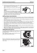
When the dump body has moved down a certain distance,
move the dump lever (3) to “FLOAT” position (C).
(When you release the lever, it returns to “FLOAT” position
(C).)
The dump body will then move down under its own weight.
REMARK
If the dump body is not completely lowered, the gear
speed is fixed at 1st anywhere the gear shift lever position
is in D to L. The reverse travel is not available when the
gear shift lever is in R position and the gear speed is fixed
at NEUTRAL. Keep the dump body lowered when travel-
ing.
PRECAUTIONS FOR OPERATION
• When traveling on roads in rain or snow, or when traveling on muddy or soft ground, consider the loaded
condition of the machine and be extremely careful not to let the tires slip or the machine spin and sink into
the ground.
• If the engine should stop when the machine is traveling, stop the machine immediately, then move the gear
shift lever to NEUTRAL position (N), and start the engine again.
• If the centralized warning lamp and pilot lamp for any “EMERGENCY” item on the machine monitor should
flash and the buzzer sounds during operation, stop the machine immediately and investigate the cause.
• When loading, be careful to load the dump body uniformly, and be particularly careful to avoid loading too
much at the front.
• When traveling on slippery road surfaces, operate the retarder control lever slowly and shift the transmis-
sion down to prevent the rear wheels from locking.
• After the machine travels in water, water may enter the front brake causing an excessive drop in the braking
efficiency. So be extremely careful. In this case, depress the brake pedal several times to dry the brake with
the friction heat of the pad and disc, then drive the machine.
PERMISSIBLE WATER DEPTH
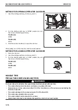
If it is obliged to drive the machine in water, do not drive it into
the water deeper than the allowable water depth (up to the in-
ner surface of rim (1)).
After completing the operations, wash the machine and lubri-
cate the parts where has entered in water.
When the machine travels in water, water may enter the drain
tank. Remove the plug (P), and drain the water which has en-
tered the tank.
MACHINE OPERATIONS AND CONTROLS
OPERATION
3-228
Summary of Contents for HD325-8
Page 2: ......
Page 13: ...FOREWORD INTRODUCTION 1 11 ...
Page 25: ...LOCATION OF SAFETY LABELS SAFETY SAFETY LABELS 2 3 ...
Page 26: ...SAFETY LABELS SAFETY 2 4 ...
Page 340: ......
Page 424: ......
Page 425: ...SPECIFICATIONS 5 1 ...
Page 429: ...ATTACHMENTS AND OP TIONS Before reading this chapter read and understand the SAFETY 6 1 ...
Page 447: ...REPLACEMENT PARTS 7 1 ...
Page 463: ......

