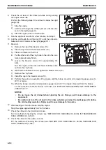
3.
Remove the nut (1) of breather assembly.
4.
Remove the cover (2).
5.
Rinse the breather element (3) in clean diesel fuel or flush-
ing oil, and remove the dirt inside.
6.
Install the breather element (3).
7.
Install the cover (2) and nut (1).
8.
Install the breather assembly.
METHOD FOR CHECKING FRAME
k
k
WARNING
When performing inspection with the dump body raised, always set the dump lever to “HOLD” position,
lock it with the dump lever lock knob, and use the dump body pivot pin.
1.
Clean the frame so that you can check them easily.
2.
Check that there is no damage to the frame.
In particular, check the shaded area in the figure. If any
cracks or other damage are found, perform the repairs.
Contact your Komatsu distributor for the repair procedure.
METHOD FOR CHECKING FOOT BRAKE PERFORMANCE
k
k
WARNING
If the machine moves when the braking capacity is being checked, it may lead to serious personal injury
or death.
If the machine moves, lower the engine speed immediately, set the gear shift lever to NEUTRAL position
(N) and set the parking brake switch to “PARKING” position.
NOTICE
• When checking, be sure to select “F2” in “F1 Start at D Position Setting”, and then set the gear shift
lever to the position D. Neglecting this can damage the inside of the transmission.
• Make the dump body seated securely before the inspection. Check that the dump body float caution
lamp is not lit.
When the dump body is not seated and the parking brake is at “TRAVEL”, the gear speed is “F1”
while the gear shift lever is at the position “D”.
1.
Check that “F2” is selected on “F1 Start at D Position Set-
ting” of user menu of the machine monitor.
MAINTENANCE
MAINTENANCE PROCEDURE
4-45
Summary of Contents for HD325-8
Page 2: ......
Page 13: ...FOREWORD INTRODUCTION 1 11 ...
Page 25: ...LOCATION OF SAFETY LABELS SAFETY SAFETY LABELS 2 3 ...
Page 26: ...SAFETY LABELS SAFETY 2 4 ...
Page 340: ......
Page 424: ......
Page 425: ...SPECIFICATIONS 5 1 ...
Page 429: ...ATTACHMENTS AND OP TIONS Before reading this chapter read and understand the SAFETY 6 1 ...
Page 447: ...REPLACEMENT PARTS 7 1 ...
Page 463: ......


