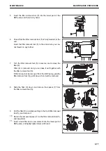
The case can be installed only when its claws (14) are cor-
rectly inserted in grooves (10) of the filter body. When in-
serting, take extreme care so that the protrusion (15) in the
case is joined together with the rubber lip (16) of the ele-
ment.
6.
Fit the ring (3) to the threaded part of the body and tighten
it with hands firmly until it stops.
7.
Tighten the ring 1/15 to 2/15 turns further (1 to 2 ridges of
the ring) by using the special wrench.
If the engine is operated with the ring tightened insufficient-
ly, oil and blowby gas may leak.
Check the KCCV hose for leakage, crack, and loose
clamp, and replace it if necessary.
METHOD FOR REPLACING DEF FILTER
k
k
WARNING
Allow parts and oils to cool to touch before you perform maintenance.
NOTICE
• Komatsu recommends using Komatsu genuine parts for replacement parts.
• If the machine is operated without the DEF filter attached, or with the filter other than Komatsu gen-
uine parts, foreign materials may enter the DEF pump and DEF injector which will cause failure of
the machine. Never operate the machine without the DEF filter attached, nor use the filter other than
Komatsu genuine parts.
• The DEF filter cannot be flushed. Flushing or regenerating of it will degrade the performance of fil-
ter, and will cause the breakage of the DEF tank. Never reuse the filter.
• Improper assembly of the DEF filter may cause leakage of the DEF. Replace the DEF filter in the cor-
rect procedure.
• DEF freezes at -11 °C. If it is frozen, replacement of the filter becomes difficult. Replace the filter
when the temperature around the DEF pump is higher than -11 °C, and in the condition that the DEF
is not frozen.
After the engine is stopped, the DEF system devices automatically purge the DEF in the DEF injector and DEF
pump and return it to the DEF tank to prevent malfunction of the devices caused by freezing of the DEF or dep-
osition of urea.
MAINTENANCE
MAINTENANCE PROCEDURE
4-75
Summary of Contents for HD325-8
Page 2: ......
Page 13: ...FOREWORD INTRODUCTION 1 11 ...
Page 25: ...LOCATION OF SAFETY LABELS SAFETY SAFETY LABELS 2 3 ...
Page 26: ...SAFETY LABELS SAFETY 2 4 ...
Page 340: ......
Page 424: ......
Page 425: ...SPECIFICATIONS 5 1 ...
Page 429: ...ATTACHMENTS AND OP TIONS Before reading this chapter read and understand the SAFETY 6 1 ...
Page 447: ...REPLACEMENT PARTS 7 1 ...
Page 463: ......


