62
INSTRUMENTS AND CONTROLS
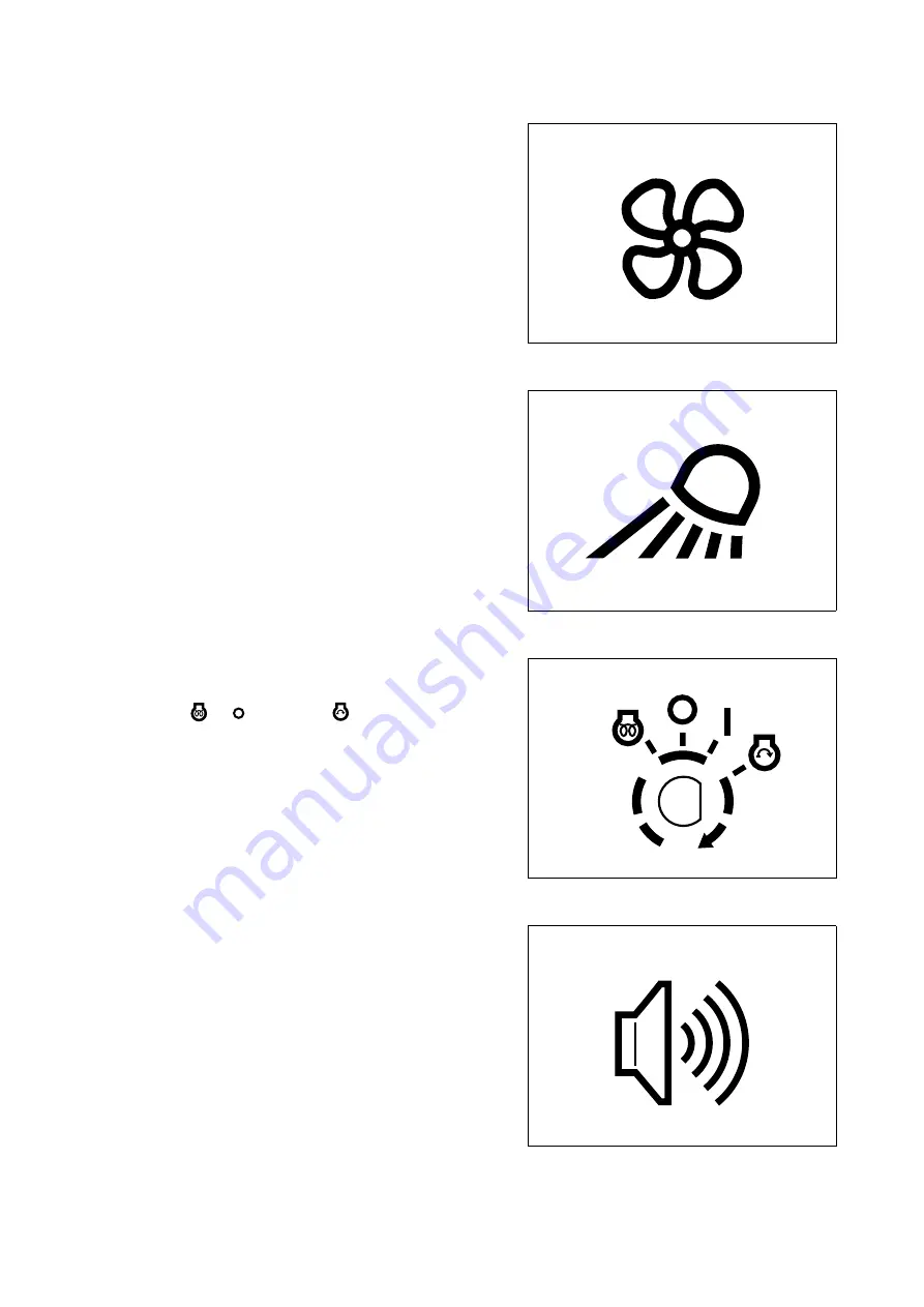
1 - FAN SWITCH
2 - WORKING LIGHT AND INSTRUMENT LIGHT
SWITCH
3 - IGNITION SWITCH
4 - ARM OVERLOAD ALARM SWITCH
(if installed)
RWA07170
This is a two-speed switch that operates the fan motor. If operat-
ed after the opening of the tap installed in the engine compart-
ment, it ensures the circulation of warm air and serves as
heating switch. (See “3.5.4 VENTILATION AND HEATING”).
RWA07180
This is a rotary switch with three positions marked by the follow-
ing symbols: OFF - 1- 2.
1) Enables the instrument light circuit
2) Enables the working light circuit
This is a rotary key switch with four positions marked by the fol-
lowing symbols: «
» - (OFF) - I - «
» (START).
For further details on the use of this switch, see “3.6.2 START-
ING THE ENGINE”.
RWA23290
This is a two-position rotary switch and, if operated, makes it
possible to define when the capacity limit has been reached.
RWA07200
Summary of Contents for PC12R-8
Page 2: ......
Page 12: ...10...
Page 20: ...18...
Page 21: ...SAFETY AND ACCIDENT PREVENTION...
Page 23: ...SAFETY NOISE AND VIBRATION PLATES 21 RWA05440...
Page 27: ...SAFETY NOISE AND VIBRATION PLATES 25 EMERGENCY EXIT LIFTING POINT RWA00190 RWA04920...
Page 55: ...THE MACHINE AND ITS OPERATIONS...
Page 88: ...86...
Page 120: ...118...
Page 121: ...MAINTENANCE...
Page 177: ...TECHNICAL SPECIFICATIONS...
Page 198: ...196...
Page 199: ...AUTHORISED OPTIONAL EQUIPMENT...


