MACHINE CONFIGURATION FOR THE INSTALLATION OF ATTACHMENTS
WEAM012101
269
6.4.2 HYDRAULIC CIRCUIT
6.4.2.1 INSTALLING AND CONNECTING THE EQUIPMENT
WARNING
q
The machine must be parked on a level surface, with the equipment resting on the ground.
q
When the connecting pins are removed or installed, chips may come off; always wear gloves, safety
goggles and helmet.
q
The change of the equipment must be carried out by two operators, who must decide together the words
and signals to be used during work.
q
Avoid using your fingers to align the holes, since the may be injured or even cut off.
q
Before carrying out any operation on the hydraulic circuit, stop the engine and completely drain the re-
sidual pressure from the pipes.
For the installation of the equipment it is necessary to connect the
mechanical constraints of the bucket as described in "3.3.13
CHANGING THE BUCKET" and to carry out the hydraulic con-
nections using the pipes provided.
After connecting the mechanical constraints, carry out the hydrau-
lic connections by proceeding as follows:
1 - Stop the engine and move the hydraulic controls in all direc-
tions, in order to release the residual pressures present in the
circuits of the machine.
2 - Press the optional equipment control pedal to release the re-
sidual pressure from the delivery pipe.
3 - Slowly loosen the hydraulic oil filling cap, in such a way as to
release the residual pressure from the tank.
4 - Remove the plugs of the quick couplers of both the machine
and the equipment.
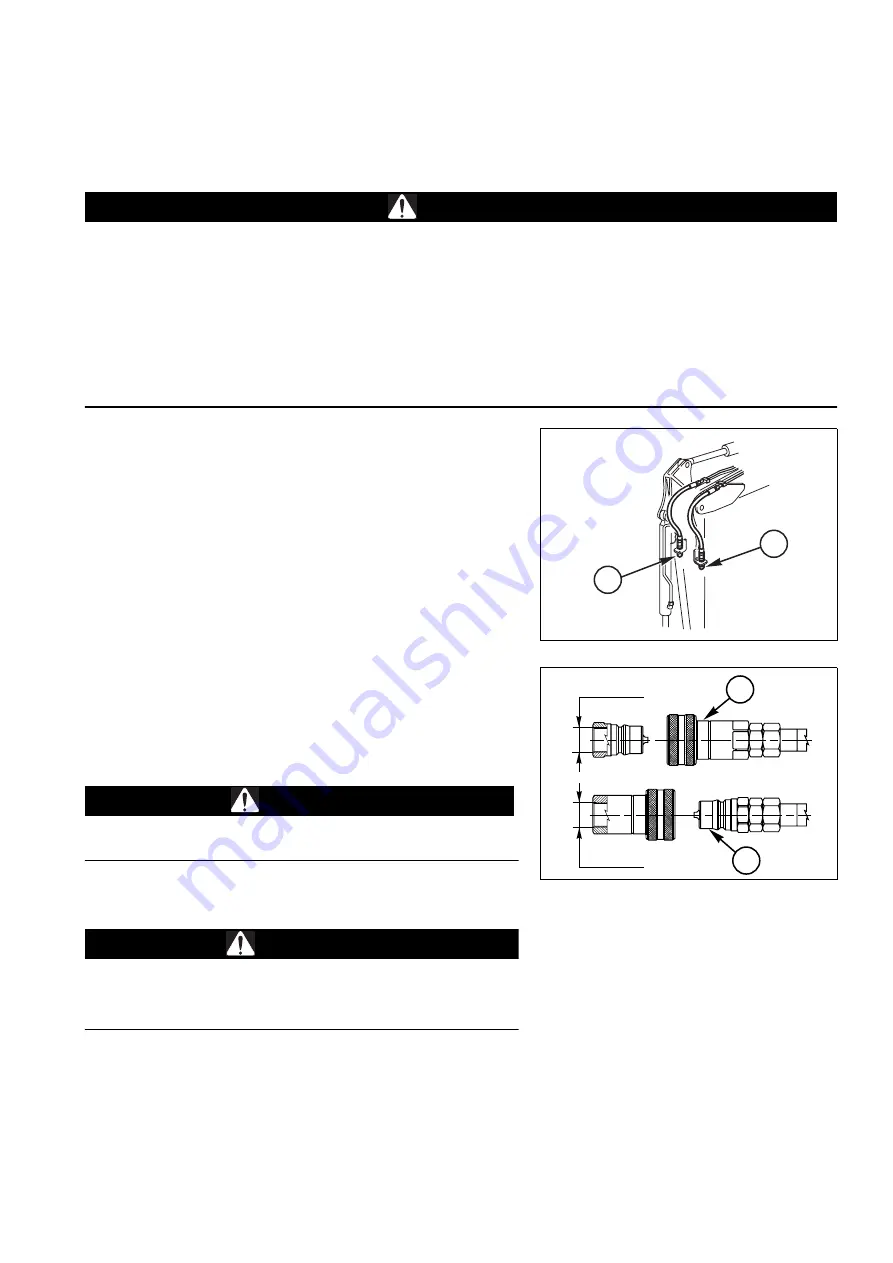
5 - Connect the right (1) and left (2) pipes. The quick couplings
must be in compliance with the ISO 7241-1 standard, series
«B».
CAUTION
q
When connecting the pipes, take care to prevent any impu-
rities from getting into them.
6 - Start the machine and perform several manoeuvres with the
equipment control pedal, in order to check the seals.
WARNING
q
Wear thick gloves and safety goggles during this check.
q
To check the system for leakages, use a piece of cardboard
or a wooden board.
6.4.2.2 MAINTENANCE
The hydraulic system does not require any maintenance operation or check other than the usual operations to be
carried out for the machine.
For tool maintenance, refer to the specific manuals.
RWA07950
2
1
RWA07960
2
1/2" GAS
1/2" GAS
1
SX
DX
Summary of Contents for PC18MR-3
Page 2: ......
Page 16: ...14 THIS PAGE WAS INTENTIONALLY LEFT EMPTY...
Page 24: ...22 PAGE INTENTIONALLY LEFT BLANK...
Page 25: ...SAFETY AND ACCIDENT PREVENTION 23...
Page 78: ...76 PAGE INTENTIONALLY LEFT BLANK...
Page 79: ...THE MACHINE AND ITS OPERATIONS 77...
Page 192: ...190 PAGE INTENTIONALLY LEFT BLANK...
Page 193: ...MAINTENANCE 191...
Page 255: ...TECHNICAL SPECIFICATIONS 253...
Page 263: ...AUTHORISED OPTIONAL EQUIPMENT 261...
Page 282: ...280 THIS PAGE WAS INTENTIONALLY LEFT EMPTY...
Page 283: ......
Page 284: ...2010 KOMATSU UTILITY EUROPE S p A All Rights Reserved Printed in Europe 06 2010...


