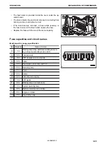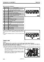
Machine with cab specification
No. Capacity
Name of circuit
(1)
5 A
Working lamp relay, additional working lamp re-
lay, and pump secondary drive switch
(2)
10 A
Solenoid valve
(3)
5 A
PPC oil pressure lock solenoid
(4)
10 A
Room lamp, radio, and windshield wiper
(5)
10 A
Travel alarm, fuel pump, and horn
(6)
10 A
Revolving lamp
(7)
10 A
Spare
(8)
20 A
Air conditioner and heater
(9)
10 A
External power supply
(10)
5 A
ACC signal
(11)
30 A
Working lamp, travel lamp, and additional work-
ing lamp
(12)
10 A
Radio, system operating lamp
(13)
10 A
Machine monitor and controller
(14)
10 A
Engine controller
(15)
10 A
Key starting relay
Fuses (16) for replacement are provided in the fuse holder. Af-
ter using fuses (16) for replacement, replenish them immedi-
ately.
Fuses (16) for replacement are 5 A, 10 A, 20 A, and 30 A each
1 piece.
FUSIBLE LINK
NOTICE
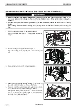
Before replacing the fuse, make sure to disconnect the quick release battery terminal (-).
For the disconnecting method of the quick release battery terminal (-), see “METHOD FOR DISCON-
NECTING QUICK RELEASE BATTERY TERMINAL (-)”.
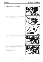
If the following phenomena occur, fusible links are suspected of disconnection. Open the engine rear cover and
cooling cover, and check the fusible link, and replace it if necessary.
• If the starting motor does not operate even when the start-
ing switch is turned to START position, the fusible link (1),
(2), or (4) may be broken.
• Fusible link (3) is suspected of disconnection if it is hard to
start the engine even after the engine preheating has been
performed when temperature is low.
EXPLANATION OF COMPONENTS
OPERATION
3-84
WENAM00150
Summary of Contents for PC30MR-5
Page 2: ......
Page 66: ...WENAM00150 ...
Page 69: ... 14 Engine rear cover 15 Cooling cover 16 Battery OPERATION GENERAL VIEW 3 3 WENAM00150 ...
Page 325: ...SPECIFICATIONS 5 1 WENAM00150 ...
Page 363: ...REPLACEMENT PARTS 7 1 WENAM00150 ...
Page 370: ...WENAM00150 ...
Page 379: ......
Page 380: ......


