4.
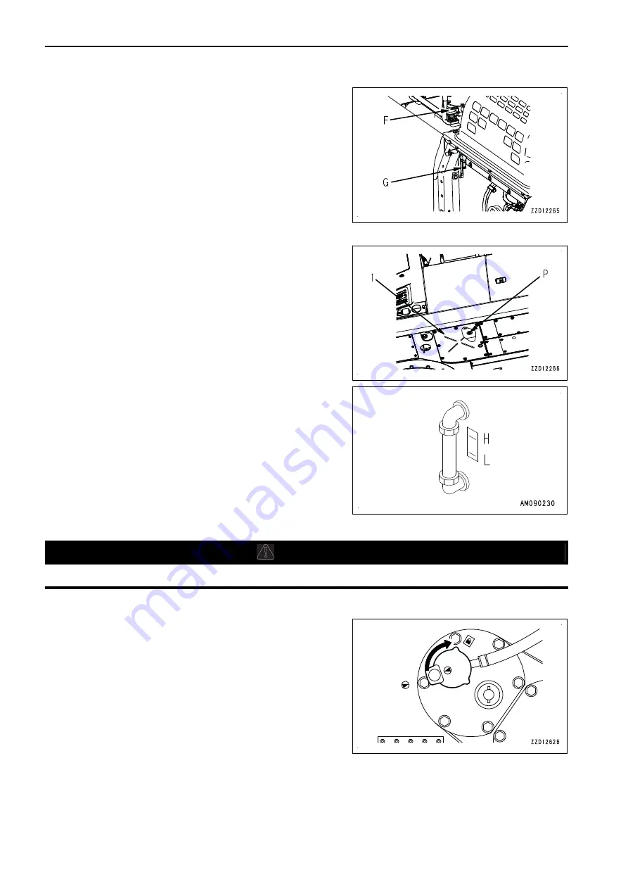
Open the door on the left side of the machine and check
sight gauge (G).
When the oil level is between the lines H and L, it is appro-
priate.
If the oil level is below level L, the hydraulic oil is insuffi-
cient. Perform the following procedure.
5.
Add oil through oil filler port (F) until the oil level comes between levels H and L of sight gauge (G).
NOTICE
Do not add oil above H line. It may damage the oil cir-
cuit and cause the oil to spurt out.
If oil has been refilled exceeding H level, swing the up-
per structure until drain plug (P) beneath the hydraulic
tank comes between the right and left tracks. Stop the
engine. After the hydraulic oil has been cooled down,
remove cover (1) and drain the excess oil through
drain plug (P) to the container for receiving the oil.
REMARK
The oil level vary with the oil temperature. Accordingly, use
the following as a guide:
• Before starting operation: Between H and L levels
(Oil temperature: 10 to 30 °C)
• Normal operation: Around H Level
(Oil temperature: 50 to 80 °C)
METHOD FOR INSTALLING HYDRAULIC TANK OIL FILLER CAP
k
k
CAUTION
If the oil filler cap is inserted in reverse, it only rotates by approximately 1/4 turns and cannot be locked.
Install the oil filler cap according to the following procedure.
1.
Match the ▲ marks on both of the oil filler cap and the
tank, and insert it.
MACHINE OPERATIONS AND CONTROLS
OPERATION
3-148
Summary of Contents for PC360LC-11
Page 2: ......
Page 22: ......
Page 76: ......
Page 344: ......
Page 425: ...SPECIFICATIONS 5 1 ...
Page 429: ...PC360NLC 11 SPECIFICATIONS SPECIFICATIONS 5 5 ...
Page 430: ......
Page 450: ...PC360LC 11 2 Piece Boom PC360NLC 11 2 Piece Boom 2 PIECE BOOM ATTACHMENTS AND OPTIONS 6 20 ...
Page 457: ...ATTACHMENTS AND OPTIONS 17M LONG REACH BOOM AND ARM 6 27 ...
Page 465: ...ATTACHMENTS AND OPTIONS SUPER LONG FRONT BOOM AND ARM 6 35 ...
Page 499: ...REPLACEMENT PARTS 7 1 ...
Page 515: ......


