background image

Summary of Contents for PC400

Page 1: ...ization from Komatsu Dresser Company It is our policy to improve our products whenever it is possible and practical to do so We reserve the right to make changes or add improvements at any time without incurring any obligation to install such changes on products sold previously Due to this continuous program of research and development periodic revisions may be made to this publication It is recom...

Page 2: ......

Page 3: ...rsonnel should read this manual thoroughly before beginning operation or maintenance Some actions involved in operation and maintenance of the machine can cause a serious accident if they are not done in a manner described in this manual The procedures and precautions given in this manual apply only to intended uses of the machine If you use your machine for any unintended uses that are not specif...

Page 4: ...azard is not avoided These safety messages or labels usually describe precautions that must be taken to avoid the hazard Failure to avoid this hazard may also result in serious damage to the machine This word is used on safety messages and safety labels for hazards which could result in minor or moderate injury if the hazard is not avoided This word might also be word for hazards where the only re...

Page 5: ...consumption controlled by an electronic control system provides an environment friendly machine 3 3 BREAKING IN THE MACHINE Your Komatsu machine has been thoroughly adjusted and tested before shipment However operating the machine under severe conditions at the beginning can adversely affect the performance and shorten the machine life Be sure to break in the machine for the initial 100 hours as i...

Page 6: ...ON On the front bottom right of the operator s cab 4 2 ENGINE SERIAL NO PLATE POSITION On the upper side of the engine cylinder head cover 4 3 TABLE TO ENTER SERIAL NO AND DISTRIBUTOR Machine serial No Engine serial No Distributor name Address Phone Service personnel for your machine I REMARKS o 4 ...

Page 7: ...tenance 1 21 8 2 During maintenance l 24 9 Position for attaching safety labels l 28 OPERATION 10 General view 2 2 10 1 General view of machine 2 2 10 2 General view of controls and gauges 2 3 11 Explanation of components 2 4 11 1 Machine monitor 2 4 11 2 Meter 2 14 11 3 Switches 2 15 11 4 Control levers pedals 2 18 11 5 Operator s seat 2 21 11 6 Dust indicator 2 21 11 7 Ceiling window 2 22 11 8 F...

Page 8: ...5 2 66 2 68 2 69 2 70 2 72 2 73 2 74 2 75 2 75 13 Transportation 2 76 13 1 Loading unloading work 2 76 13 2 Precautions for loading 2 78 13 3 Precautions for transportation 2 78 13 4 Method of lifting chassis machines equipped with lifting hook 2 79 13 5 Diving the machine 2 80 13 6 Procedure for increasing or reducing track frame gauge 2 82 14 Cold weather operation 2 84 14 1 Precautions for low ...

Page 9: ...ts 3 19 21 1 introduction of necessary tools 3 19 21 2 Torque list 3 20 22 Periodic replacement of safety critical parts 3 21 23 Maintenance schedule chart 3 23 23 1 Maintenance schedule chart 3 23 23 2 Maintenance interval when using hydraulic breaker 3 25 24 Service Procedure 24 1 Initial 250 hours service 24 2 When required 24 3 Check before starting 24 4 Every 100 hours service 24 5 Every 250 ...

Page 10: ... 30 1 Control panel 30 2 Operation 30 3 Inspection and maintenance Operation of attachments 5 12 Introduction of attachments 32 1 Specification use 32 2 Attachment installation combination table 32 3 Selection of track shoes 32 4 Selection of bucket teeth 32 5 Handling clamshell bucket Extending machine service life 33 1 Hydraulic breaker 33 2 Power ripper 33 3 Fork grab 33 4 Grapple bucket 33 5 S...

Page 11: ...nts and controls 6 3 35 1 Switches 6 3 35 2 Control levers pedals 6 5 36 Precautions for machine operation 6 7 36 1 Precautions during operation 6 7 37 Maintenance 6 10 37 1 Every 10 hours service 6 10 38 Transportations 6 l 1 39 Specifications 6 12 o 9 ...

Page 12: ......

Page 13: ...SAFETY A WARNING Read and follow all safety precautions Failure to do so may result in serious injury or death This safety section also contains precautions for optional equip ment and attachments l l ...

Page 14: ......

Page 15: ... AE096630 MOUNTING AND DISMOUNTING I l NEVER jump on or off the machine NEVER get on or off a moving machine l When mounting or dismounting always face the machine and use the handrails machine or track frame steps and track shoes Do not hold any control levers when getting on or off the machine Ensure safety by always maintaining at least three point contact of hands and feet with the handrails s...

Page 16: ...PRECAUTIONS WHEN HANDLING AT HIGH TEMPERATURES Immediately after operations are stopped the engine coolant engine oil and hydraulic oil are at high temperatures and are still under pressure Attempting to remove the cap drain the oil or water or replace the filters may lead to serious burns Always wait for the temperature to go down and follow the specified procedures when carrying out these operat...

Page 17: ...roved respirator if necessary CRUSHING OR CUTTING PREVENTION l Do not enter or put your hand or arm or any other part of your body between movable parts such as between the work equipment and cylinders or between the machine and work equipment If the work equipment is operated the clearance will change and this may lead to serious damage or personal injury A0066090 l Be sure fire extinguishers hav...

Page 18: ...protective structure in place Also place a laminate coating sheet over the windshield The above comments are made with regards to typical working conditions By all means you should put on other guards if required by conditions at your particular site For details of safety guards please contact your Komatsu distributor Also even for other types of work if there is any danger of getting hit by falli...

Page 19: ... control lever is shifted to LOWER After the engine is stopped set the safety lock lever to the lock position and also lock the attachment pedal with the lock pin When releasing the pressure inside the work equipment circuit on machines equipped with an accumulator follow the procedure given in the inspection and maintenance section Method of releasing pressure See 11 16 HANDLING ACCUMULATOR The a...

Page 20: ...of water before operating in water or crossing a river NEVER be in water which is in excess of the permissible water depth Permissible water depth See 12 11 PRECAUTIONS FOR OPERATION FIRE PREVENTION Thoroughly remove wood chips leaves paper and other flammable things accumulated on the engine compartment They could cause a fire Check fuel lubrication and hydraulic systems for leaks Have any leaks ...

Page 21: ...0 4 PRECAUTIONS FOR MIRRORS WINDOWS AND LIGHTS 1 l Remove all dirt from the surface of the windows and lights to ensure that you can see well l Adjust the rear view mirror so that you can see clearly from the operator s seat and always keep the surface of the mirror clean If any glass is broken replace it with a new part l Check that the head lamps and working lamps are installed to match the oper...

Page 22: ...RECTION BEFORE STARTING MACHINE Before operating the travel lever check the direction of the track frame If the sprocket is at the front the travel lever must be operated in the opposite direction Travel operations See 12 4 MOVING MACHINE OFF Travel in reverse direction Sprocket AE096660 CHECK THAT NO ONE IS IN AREA BEFORE SWINGING OR TRAVELING IN REVERSE Always position a signalman in places in d...

Page 23: ... Never travel over obstacles which make the machine tilt strongly IO or more Travel posture INCORRECT f 40 5Ocm 16to 20 In AE081190 AE081200 TRAVELING 1 Traveling on hills banks or slopes that are steep could result in the machine tipping over or slipping On hills banks or slopes carry the bucket closer to the ground approximately 20 to 30 cm 8 to 12 in above the ground In case of emergency quickl...

Page 24: ...aintain the safe distance given below between the machine and the electric cable l The following actions are effective in preventing accidents 1 Wear shoes with rubber or leather soles 2 Use a signalman to give warning if the machine approaches too close to the electric cable l If the work equipment should touch the electric cable the operator should not leave the operator s compartment l When car...

Page 25: ... icy roads even a slight slope may cause the machine to slip to the side so always travel at low speed and avoid sudden starting stopping or turning l When there has been heavy snow the road shoulder and objects placed beside the road are buried in the snow and cannot be seen so always carry out snow clearing operations carefully 4 WORKING ON LOOSE GROUND 1 l Avoid operating your machine too close...

Page 26: ...il on slope See 12 12 PRECAUTIONS WHEN TRAVELING UP OR DOWN HILLS PARKING THE MACHINE Park on level ground whenever possible If not possible block the tracks lower the bucket to the ground and thrust the bucket in the ground CORRECT Thrust the bucket AE096760 When parking on public roads provide fences and signs such as flags or lights on the machine to warn passersby to be careful Be sure that th...

Page 27: ...positioned and fastened and that the two sides are at the same level as one another Be sure the ramp surface is clean and free of grease oil ice and loose materials Remove dirt from the machine tracks NEVER correct your steering on the ramps If necessary drive away from the ramps and climb again Swing the upper structure with extreme care on the trailer to avoid a possible accident caused by body ...

Page 28: ...minals through accidental contact with metallic objects such as tools across the terminals When removing or installing check which is the positive I terminal and negative 1 terminal Tighten the battery cap securely Tighten the battery terminals securely Loosened terminals can generate sparks and lead to an explosion A0055100 A00551 10 ALWAYS wear safety glasses or goggles when starting the machine...

Page 29: ......

Page 30: ...rmality before starting operations o Check that there are no cracks or deformation in the lifting equipment o Check that there is no abnormality in the stopper device l When performing lifting operation securely fit the wire rope on the special lifting hook PRECAUTIONS FOR l After carrying out a preliminarily inspection of ground conditions select a flat solid location Confirm that the machine can...

Page 31: ...e performing lifting operation designate an operation supervisor Always execute operation according to his instructions o Execute operating methods and procedures under his direction o Select a person responsible for signaling Operate only on signals given by such person HANDING OF WIRE ROPES ETC l Wear leather gloves when handling wire ropes 1 19 ...

Page 32: ...AT 1 l Never leave the operator s seat while lifting a load l Operation exceeding machine performance may result in accident or failure l Carry out lifting operation within specified load limit l Never carry out operations which may damage the machine such as overload or over impact load l Never drag a load laterally or longitudinally nor retract the arm otherwise a dangerous situation may result ...

Page 33: ...09963 03000 AE081330 PROPER TOOLS l Use only tools suited to the task Using damaged low quality faulty or makeshift tools could cause personal injury Tools See 21 1 INTRODUCTION OF NECESSARY TOOLS A0055120 l Replace the following fire related components periodically Fuel system Fuel hose spilling hose and fuel tube cap Hydraulic system Pump outlet hose and front and rear pump branch hoses l Replac...

Page 34: ...wo workers One worker should sit in the operator s seat so that he can stop the engine immediately if necessary He should also be extremely careful not to touch any lever by mistake Touch the levers only when they have to be operated The worker carrying out the maintenance should be extremely careful not to touch or get caught in the moving parts HEAT OFF I START Free AE081340 AE096630 RULES TO FO...

Page 35: ... radiator stop the engine and allow the engine and radiator to cool down before adding the water l Slowly loosen the caps to relieve pressure before removing the caps l When checking fuel oil coolant or battery electrolyte always use lighting with anti explosion specifications If such lighting equipment is not used there is danger of explosion l 23 ...

Page 36: ...s lower all movable work equipment to the ground or to their lowest position before performing service or repairs under the machine Always block the track shoes of the machine securely Never work under the machine if the machine is poorly supported A0055140 4 KEEP THE MACHINE CLEAN 1 l Spilled oil or grease or scattered tools or broken pieces are dangerous because they may cause you to slip or tri...

Page 37: ... fuel hoses or oil hoses If fuel or oil leaks it may cause a fire PRECAUTIONS WITH HIGH PRESSURE OIL Do not forget that the work equipment circuits are always under pressure Do not add oil drain oil or carry out maintenance or inspection before completely releasing the internal pressure If oil is leaking under high pressure from small holes it is dangerous if the jet of high pressure oil hits your...

Page 38: ...ubricating oil level adding oil see 24 3 7 PERIODIC MAINTENANCE Changing oil replacing filters see 24 5 8 PERIODIC MAINTENANCE r l PRECAUTIONS WHEN USING HIGH PRESSURE GREASE TO ADJUST TRACK TENSION I 1 Grease is pumped into the track tension adjustment system under high pressure If the specified procedure for maintenance is not followed when making adjustments the plug or grease fitting may fly o...

Page 39: ... Never dump waste oil in a sewer system rivers etc l Always put oil drained from your machine in containers Never drain oil directly on the ground o Obey appropriate laws and regulations when disposing of harmful objects such as oil fuel coolant solvent filters batteries and others INCORRECT A0055220 1 27 ...

Page 40: ...ace them with a new label There are other labels in addition to the safety labels listed as follows so handle them in the same way Safety labels may be available in languages other than English To find out what labels are available contact your Komatsu distributor POSITION FOR ATTACHING SAFETY LABELS AE096800 AE096810 l 28 ...

Page 41: ...WORK EclLwMENT TO THE LEVEL MACHINE GROUND AND LOCKTHE LEVER ALWAYS BLOCK TRACKS WHEN PARKING 3 DO NOT GO UNDER MACHINE WHEN IT IS MAtHlNE ON ASLOPE RAISED SY THE WORK EClLwMEM WHENADJUSTING TRACKTENSION NEVER LOOSEN VALVE MORE THAN ONE TURN TO SHUT DOWN ENGINE OPERATlON DLE FOF GREASE IS UNDER HIGH PRESSURE AND W TES THEN TURN KEY SW 73 TO MAY SPURT OUT SEE OPERATION MAINTENANCE MANUAL FOR DETAIL...

Page 42: ...LVE MOUNTED ON THE ACCUMULATOR WHEN THERE IS NO SUCH VALVE REMOVE THE ACCUMULATOR S GAS FILLING VALVE CAP AND RELEASE THE GAS BY DEPRESSING THE VALVE CORE PIN WITH SUITABLE TOOL SCREW DRIVER 1 TYPE OF GAS NITROGEN 2 WORKING PRESSURE MAXIMUM 1000 psi 70 kg cm2 3 TESTING PRESSURE 1500 psi 105 kg cm2 205 00 71570 3 Warning for hot water 09668 I 3000 4 Warning for fan belt 09667 03000 WHILE ENGINE IS ...

Page 43: ... window 205 00 63350 WHEN RAISING FRONT WINDOW PUSH WINDOW UP TO HOLD WITH CATCH AT REAR OF CEILING CHECK WINDOW IS SECURELY IN POSITION THEN LOCK WITH RIGHT AND LEFT LOCK PINS 205 00 63350 Warning for gas filling 205 00 71441 WARNING J It Ah CONTAINS NITROGEN GAS DO NOT LOOSEN CAP DO NOT FILL WITH OXYGEN OR EXPLOSIVE GASES 205 00 71441 I 31 ...

Page 44: ...1 32 ...

Page 45: ...OPERATION ...

Page 46: ...ENERAL VIEW OF MACHINE If directions are indicated in this section they refer to the directions shown by the arrows in the diagram below E C Arm cylinder I Boom B oom cylinder rocket I Track frame Bulket Track shoe Idler 2 2 ...

Page 47: ......

Page 48: ...095850 This monitor system consists of monitor lamps 01 meter group switch group 0 A BASIC CHECK ITEMS 11 1 1 This displays the basic items that should be checked before starting the engine If there is any abnormality the appropriate monitor lamp will flash NOTICE If engine started lamp will go off even if there is an abnormality When carrying out checks before starting do not simply rely on the m...

Page 49: ...h need to be repaired immediately are displayed D METER DISPLAY PORTION 11 1 4 This portion consists of pre heating monitor swing lock monitor engine water temperature gauge fuel gauge and display E SWITCHES 11 I 5 This consists of lamp switch cab heater switch mode selector switch wiper switch alarm buzzer stop switch and travel speed switch Functional check of the machine monitor system When the...

Page 50: ...ION to carry out the checks 1 RADIATOR WATER LEVEL This warns that the radiator cooling water level is too low If the monitor lamp flashes check the cooling water level in the radiator and reserve tank and add water AD096870 2 ENGINE OIL LEVEL This warns that the oil level in the engine oil pan is too low If the monitor lamp flashes check the oil level in the engine oil pan and add oil AD096880 2 ...

Page 51: ...e 1 CHARGE LEVEL This monitor indicates an abnormality in the charging system while the engine is running If the monitor lamp flashes check the V belt tension If any abnormality is found see 16 6 OTHER TROUBLE REMARK While the starting switch is ON the lamp will remain lit and will go off once the engine is started IJ AD096890 _ I 1 AD096900 2 FUEL LEVEL If the fuel drops below 43 liters I 1 4 US ...

Page 52: ...ge enters the green range AD096920 2 RADIATOR WATER LEVEL If the radiator water level drops the monitor lamp flashes Stop the engine check the radiator water level and add water if neces sa ry AD096670 3 ENGINE OIL PRESSURE If the engine oil pressure drops below the normal pressure the monitor lamp flashes At this item stop the engine and inspect it according to 16 6 OTHER TROUBLE REMARK While the...

Page 53: ...ng operation the overheat prevention system will be actuated If the red range flashes engine water temperature monitor flashes and alarm buzzer sounds at same time the overheat prevention system will be actuated The overheat prevention system acts as follows When red range lights up The power mode switched to L mode for each working mode and engine water temperature monitor flashes When red range ...

Page 54: ...ng the engine turn the starting switch ON and check that the monitor lamps on items A B C and D and the meters light up 3 ENGINE PRE HEATING MONITOR This monitor lamp indicates the pre heating time required when starting the engine at an ambient temperature below 0 C The monitor lamp lights when the starting switch is turned to HEAT position and flashes after about 30 seconds to show that the pre ...

Page 55: ...k F O finishing operation mode lights up This is used for leveling or grading work L O lifting operation mode lights up This is used for fine control operations When starting the engine G O general operation mode is auto matically selected Each time the switch is pressed the mode selection changes 2 POWER MODE SWITCH SELECTED MODE This switch is used to set output force for the work equipment to m...

Page 56: ...perated when the machine is traveling the machine may deviate even when traveling in a straight line This is used to select the two travel speeds lights up Low speed travel I lights up High speed travel AD097040 When the engine is started the travel speed is automatically set to Lo When traveling in the travel speed is automatically switched to low speed travel to match the travel surface on soft ...

Page 57: ...s up Intermittent wiper operation Hi lights up Continuous wiper operation OFF Wipers stopped J AD097060 Lo Hi 00 8 CAB HEATER SWITCH This switch is used to heat the operator s compartment The flow rate of the hot air can be set to two levels Lo lights up Low wind speed Hi lights up High wind speed OFF Cab heater stopped l The cab is heated by means of warm water from the engine Accordingly heating...

Page 58: ...e intervals using this display The service meter advances while the engine is running even if the machine is not traveling While the engine is running the operation display at the top inside of the meter will rotate to show that the meter is advancing AD097100 The meter will advance by 1 for each hour of operation regardless of the engine speed 2 14 ...

Page 59: ...ctrical circuits except the START and HEAT circuit START position This is the engine start position Keep the key at this position during cranking Immediately after starting the engine release the key which will automatically return to the ON position HEAT preheat position When starting the engine in winter set the key to this position When the key is set to the HEAT position the pre heating monito...

Page 60: ...nnot swing ON position actuated OFF canceled The swing lock is always applied and the upper structure will not swing even if the swing is operated In this condition the swing lock lamp lights up OFF position canceled 1 Front of z AE081660 The swing lock is applied only when all work equipment control levers are at neutral when any work equipment control lever is operated it is canceled The swing l...

Page 61: ...he left work equipment control lever is being pressed max approx 8 set the maximum power is increased 6 HORN BUlTON When this button is pressed the horn will sound 7 ROOM LAMP SWITCH When this switch is moved to ON position room lamp will light AE097130 AE097140 AE097150 ON 0 OFF I AE081710 2 17 ...

Page 62: ... lock lever is not placed securely in the LOCK position the control levers may not be properly locked Check that the situation is as shown in the diagram When the safety lock lever is lowered take care not to touch the work equipment control lever If the safety lock lever is not properly locked at the down position the work equip ment and swing will move creating a potentially dangerous situation ...

Page 63: ...erious accident With the track frame facing to the rear the machine will move in the reverse direction by forward traveling and in the forward direction by reverse traveling When the travel lever is used check to see if the track frame is facing forward or backward If the sprocket is located to the rear the track frame is facing forward 0 0 N FORWARD The lever is pushed forward The pedal is angled...

Page 64: ... the boom and the bucket will be retained in the position in which they stop For levers 2 3 and 4 the engine speed changes as follows because of the auto deceleration mechanism When the travel lever and work equipment control levers are at neutral even if the fuel control dial is above the mid range position the engine speed will drop to a mid range speed If any of the levers are operated the engi...

Page 65: ...the engine and lock the left and right work equipment control levers with the lock lever Up down adjustment range 110 mm 5 stages 1 Turn knob to the left to loosen it then pull up lever 0 2 Align the pin hole in the mount base with the seat bracket pin hole at the desired height then return lever and insert pin 0 Turn knob to the right to fix the seat in position AE097210 AE097230 11 6 DUST INDICA...

Page 66: ...ree AE096630 When opening 1 Lock the safety lock lever securely 2 Check for any ceiling window movement by pulling lock knob located on front side then push up and open the ceiling window grasping grip 0 When closing Close the ceiling window grasping grip and lock it with lock knob 0 If the lock cannot be applied open and close the ceiling window again REMARK When opening or closing the ceiling wi...

Page 67: ...e roof of the operator s compartment When opening 7 a WARNING 7 When the front window IS open there IS danger that It WIII fall so always lock it with left and right lock pins 1 Place the work equipment on flat ground and stop the engine 2 Securely lock the safety lock lever 3 Disconnect wiper motor cable from receptacle 4 Pull lock pins at the top left and to the inside to release the lock sides ...

Page 68: ... the window lower it slowly and be careful not to get your hand caught Place the work equipment on flat ground and stop the engine 2 Securely lock the safety lock lever 3 Release the lock pin 4 Hold the grip at the bottom of the front window with your left hand and the grip at the top with your right hand release the lock of catch with your right thumb then pull the top grip slowly and lower the f...

Page 69: ...dow can be removed I AE097240 Store the removed bottom part of the front window at the rear 1 of the opertor s cab and lock with lock pins 0 11 9 DOOR LOCK Use the door lock to fix the door in position after opening it 1 The door will become fixed in place when it is pressed against catch 0 2 To release the lock press knob down at the left side of the operator s seat to release the catch When fixi...

Page 70: ...ock OP AE097250 To lock the cap 1 Turn the cap into place 2 Turn the key counterclockwise and take the key out Match mark on the cap AE097260 Insert the key as far as it will go If the key is turned before it is inserted all the way it may break Shoulder AE097270 11 10 2 METHOD OF OPENING AND CLOSING HYDRAULIC TANK FILLER CAP To open the cap 1 Insert the key in the cap then turn the key counterclo...

Page 71: ...CONTROL Use this knob to adjust the tone as desired When it is turned to the right the high tones will be emphasized and when it turned to the left the high tones will be cut resulting in a mellow tone 3 POWER SWITCH VOLUME CONTROL Press the knob to turn on or off the radio When it is turned to the right the sound level will increase and vice versa 4 STATION SELECTOR BUTTONS 5 buttons By pressing ...

Page 72: ... reduce the input as far as possible before carrying out alignment I AE097320 11 11 3 PRECAUTIONS WHEN USING RADIO l To prevent possible breakdown keep water well away from the speaker case and interior of the radio In particular close the window during rain or when washing the machine l Do not wipe the dial plate or knobs with benzine or paint thinners etc Always use a dry soft cloth if the radio...

Page 73: ...ngine governor controller I 10 A Monitor buzzer 1 15 A 1 Heater air conditioner cooler 0 10 A Right head lamp working lamp 10 A Room lamp radio 0 10 A Wiper motor horn window washer I 10 A Cigarette lighter 1 10 A 1 Battery relay electric heater relay start signal 10 A Spare swing flasher Spare fuses two of IOA one of 15A are kept in the spare fuse box 11 13 MONITOR PANEL AE097330 AD097340 The ang...

Page 74: ...se 11 15 CONTROLLERS A pump controller and electronic governor controller are provided NOTICE l Never splash or spill water mud or drink over the controllers as this may cause a fault l If a fault occurs in the controller do not attempt repair but consult your Komatsu distributor PUMP CONTROLLER This informs of the location of any abnormality in the electronic control system of the pump A 2 digit ...

Page 75: ...iven in the table above are displayed accord ing to the input mode and machine condition Engine speed signal monitor flashes according to the engine speed At 2000 rpm it flashes approx 20 times IO set When switching the input the following display is given When switching input Display When electric power is switched on 0 5 set c Switching travel speed Hi r Lo o Auto deceleration switch Swing lock ...

Page 76: ...the electrically controlled throttle Green and red LEDs Light Emitting that shows the location of the abnormality When the electrically controlled throttle is normal the display is as given in the table If the LEDs light up to show an abnormality then contact your Komatsu distributor for repairs When normal Red I Green 0 Red 2 32 ...

Page 77: ...llowing precautions l Never make any hole in the accumulator or expose it to flame or fire l Do not weld any boss to the accumulator l When disposing of the accumulator it is necessary to release the gas from the accumulator so please contact your Komatsu distributor This machine is equipped with the accumulator in the control circuit The accumulator is a device to store the pressure in the contro...

Page 78: ...position Move the work equipment control lever and the attachment control pedal to full stroke back and forth right and left so as to release the pressure in the control circuit Move the safety lock lever to the lock position Lock the control lever and attachment control pedal The pressure however will not be completely released so when the accumulator is re moved in the control circuit gradually ...

Page 79: ... the engine look around the machine and under the machine to check for loose nut or bolts or leakage of oil fuel or coolant and check the condition of the work equipment and hydraulic system Check also for loose wiring play and collection of dust at places which reach high temperatures Always carry out the items in this section before starting the engine each day 10 5 a 2 5 2 l 0 I q 1 5 67 9 4 5 ...

Page 80: ...e undercarriage track sprocket idler guard for dam age wear loose bolts or leakage of oil from rollers Check for damage to handrail loose bolts Repair any damage and tighten any loose Check for damage to gauges monitor loose bolts Check that there is no damage to the gauges and monitor in the operator s cab If any abnormality is found replace the parts Clean off any dirt on the surface Clean rear ...

Page 81: ...and radiator filler to the FULL level 2 After adding water tighten the caps securely 3 If the reserve tank becomes empty first inspect for water leaks and then fill the radiator and the reserve tank with water CHECK OIL LEVEL IN ENGINE OIL PAN ADD OIL Open the rear cover on the machine Remove dipstick and wipe the oil off with a cloth Insert dipstick fully in the oil filler pipe then take it out a...

Page 82: ...FUEL g WARNING When adding fuel never let the fuel overflow This may cause a fire If you spill fuel thoroughly clean up any spillage 1 Use sight gauge on the front face of the fuel tank to check that the tank is full 2 if the fuel level is not within the sight gauge add fuel through filler port while watching sight gauge 0 Fuel capacity 550 f 145 US gal 121 UK gal For details of the fuel to use se...

Page 83: ...e engine move each control lever for work equipment and travel to the full stroke in all 1 Iul directions to release the internal pressure Check sight gauge 0 The oil level is normal if between the H and L marks AE082200 NOTICE Do not add oil if the level is above the H line This will damage the hydraulic equipment and cause the oil to spurt out 4 If the level is below the L mark remove the upper ...

Page 84: ... the electric wiring Check also for loose terminals and tighten any loose parts Check the following points carefully l Battery 0 Starting motor l Alternator Please contact your Komatsu distributor for investigation and correction of the cause etc around the battery may cause fire so always check and When carrying out walk around checks or checks before starting always check if there is any accumul...

Page 85: ...in in 9 steps Adjustment of reclining seat I Pull lever up After the seat back is set to the optimum position easy operation release the lever Up down adjustment of seat When carrying out the adjustment stop the engine and lock the left and right work equipment control levers with the lock lever Up down adjustment range 110 mm 5 stages 1 Turn knob to the left to loosen it then pull up lever 0 2 Al...

Page 86: ...rting switch 0 turn the key to the ON position then carry out the following checks I The buzzer will sound for approx 1 set and the following monitors and gauges will light up for approx 3 sec l Radiator water level monitor l Engine oil level monitor l Hydraulic oil level monitor l Charge level monitor l Fuel level monitor 0 l Engine water temperature monitor l Engine oil pressure monitor l Engine...

Page 87: ... monitors will go out l l 2 Engine water temperature gauge Fuel gauge I Press lamp switch to turn on the head lamps If the lamps do not light up there is probably a broken bulb or disconnection in the wiring so contact your Komatsu distributor for repairs AD097060 2 43 ...

Page 88: ...e will not start wait for at least 2 minutes before trying to start the engine again 1 Set fuel control dial 0 at the low idling MINI position 2 Turn the key in starting switch to the START position The engine will start AE097590 HEtT 0 START AE082310 3 When the engine starts release the key in starting switch 0 The key will return automatically to the ON position HEAT OTF 1 ON I START AE082320 2 ...

Page 89: ...in low temperatures do as follows Do not keep the starting motor rotating continuously for more I AD097600 1 Set fuel control dial iJ at the low idling MINI position 2 Hold the key in starting switch at the HEAT position and check that preheating monitor lights up After about 30 seconds preheating monitor lamp will flash for about 10 seconds to indicate that preheating is finished AE097590 AE09761...

Page 90: ...ing switch 0 The key will return automatically to the ON position HEfiT O F ON I START AE082320 12 2 3 SPECIAL STARTING When starting after running out of fuel fill with fuel then fill the fuel filter cartridge with clean fuel and bleed the air from the fuel system before starting For details of bleeding the air see 24 6 1 REPLACE FUEL FILTER CARTRIDGE 2 46 ...

Page 91: ...warming up operation This will help to extend the machine life l Do not suddenly accelerate the engine before the warming up operation is completed Do not run the engine at low idling or high idling continuously for more than 20 minutes This will cause leakage of oil from the turbocharger oil supply piping If it is necessary to run the engine at idling apply a load from time to time or run the eng...

Page 92: ... earlier NOTICE When the work equipment is retracted take care that it does not interfere with the machine body or ground After carrying out the warming up operation check that each gauge and monitor lamp is in the following condition Engine water temperature gauge 0 Inside green range Fuel gauge 0 Inside green range Engine water temperature monitor OUT Radiator water level monitor OUT Engine oil ...

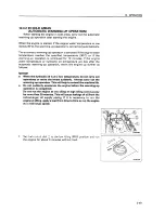
Page 93: ... automatic warming up operation warm the engine up further as follows NOTICE l When the hydraulic oil is at a low temperature do not carry out operations or move the levers suddenly Always carry out the warming up operation This will help to extend the machine life l Do not suddenly accelerate the engine before the warming up operation is completed Do not run the engine at low idling or high idlin...

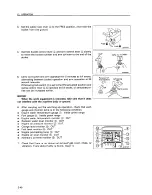
Page 94: ...rol lever and arm control lever slowly to move the bucket cylinder and arm cylinder to the end of their stroke Operate the bucket for 30 seconds and the arm for 30 seconds in turn fully for 5 minutes AE097640 REMARK Turn swing lock switch ON ACTUATED and operate the lever AE097650 to make the oil temperature rise more quickly ON actuated NOTICE When the work equipment is retracted take care that i...

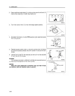
Page 95: ...ER Arm operation IN t OUT Bucket operation CURL H DUMP Swing operation LEFT w RIGHT Travel Lo operation FORWARD ts REVERSE REMARK In the above operation is not carried out there may be a delay in response when starting or stopping each actuator so continue the operation until it becomes normal 9 Use working mode switch on the monitor panel to select the working mode to be used ADO97010 2 51 ...

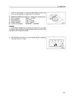
Page 96: ...cy to lower the engine speed to low idling cancel the automatic warming up operation as fol lows 1 Turn fuel control dial to the full speed MAX position and hold it for 3 seconds AE097590 2 When fuel control dial is returned to the low idling MIN position the engine speed will drop 2 52 ...

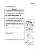
Page 97: ...rs carefully Avoid abruptly operating the traveling and steering levers with the fuel control lever fully open as this will cause the machine to move off suddenly Always set the travel speed selector switch to LO low when high resistance to traveling causes the engine speed to drop for example when climbing slopes or traveling over rough ground 1 Set swing lock switch to the ON actuated position a...

Page 98: ...versed When moving off check that the area around the machine is safe and sound the horn before moving Clear all personnel from the machine and the area Clear all obstacles from the path of the machine Use extreme care when reversing the machine Note there is an blind spot behind the machine If the lever is moved inside the deceleration range engine speed will suddenly rise Operate the levers care...

Page 99: ...the ground Operate right and left travel levers or right and left travel pedals as follows When the sprocket is at the rear of the machine Pull levers backward slowly or depress the rear part of pedals to move the machine off When the sprocket is at the front of the machine Push levers forward slowly or depress the front part of to move the machine off pedals Lock Sprocket AE097750 rocket AE09776o...

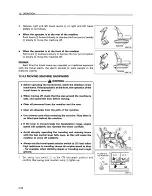
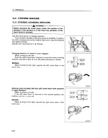
Page 100: ...levers as follows Changing direction of machine when stopped When turning to the left Push the right travel lever forward to travel left when traveling forward and pull it back to turn left when traveling in reverse REMARK When turning to the right operate the left travel lever in the same way Steering when traveling left and right travel levers both operated in same direction When turning to the ...

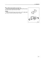
Page 101: ...hen turning left using counter rotation pull the left travel lever back and push the right travel lever forward REMARK When turning right using counter rotation pull the right travel lever back and push the left travel lever forward AE097800 2 57 ...

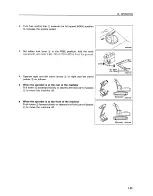
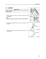
Page 102: ... If the control lever is touched by accident the work equipment or the machine may move suddenly and this may lead to a serious accident Before leaving the operator s compartment always set the safety lock lever securely to the LOCK position Thrust the bucket AE096750 Fr eew c Lock AE096630 1 Put the left and right travel levers in the neutral position then stop the machine 2 Lower the engine spee...

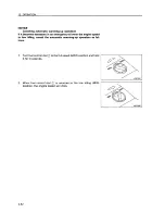
Page 103: ...n swing lock switch OFF CANCELED NOTICE Check that swing lock monitor goes out at the same time AE097820 2 Operate left work equipment control lever to swing the upper structure Left swing ight swing AE097830 3 When not operating the swing turn swing lock switch ON ACTUATED ON actuated OFF canceled Front of machine AE082390 2 59 ...

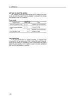
Page 104: ...ed they automatically return to the neutral position and the work equipment is held in place l If the work equipment control lever is returned to the neutral position when the machine is stopped even if the fuel control dial is set to FULL the auto deceleration mechanism will act to reduce the engine speed to a mid range speed REMARK If the levers are operated within 15 seconds after stopping the ...

Page 105: ...ode The most effective mode for the type of work is set with the basic mode working mode switch l The table below shows the condition of the power mode and auto deceleration and the most suitable type of work for each setting Basic mode Selected mode Power Auto de Applicable work Working mode mode celeration Heavy duty control H mode ON Large digging and loading production operation mode H 0 in a ...

Page 106: ... H S Reduction in fuel consumption General finishing operation HtS Increase in speed mode S L Reduction in fuel consumption Lifting operation mode StL Increase in speed Auto deceleration If the auto deceleration is always actuated it improves fuel consumption so we recommend that it always be used However if the control levers are operated in small movements the engine speed changes greatly so it ...

Page 107: ...ns using travel force Do not leave the bucket dug into the ground and use the travel force to excavate This will bring excessive force to bear on the rear of the machine Precautions when operating hydraulic cylinders to end of stroke If the cylinder is operated to the end of its stroke during opera tions force will be brought to bear on the stopper inside the cylinder and this will reduce the life...

Page 108: ...r shifting from forward to reverse or vice versa Avoid sudden lever shifting change such as sudden stopping from near top speed lever release operation NCORRECT AE09793 NCORRECT INCORRECT Forward Neutral AE082620 NOTICE Note that the following phenomena are not faults l When the arm is pulled back it will sometimes stop when becomes more or less vertical l The arm may sometimes stop when the bucke...

Page 109: ...peed When Hi speed traveling set the idler in the forward direction INCORRECT Ap AEOll200 PERMISSIBLE WATER DEPTH NOTICE When driving the machine out of water if the angle of the machine exceeds 15 the rear of the upper structure will go under water and water will be thrown up by the radiator fan This may cause the fan to break Be extremely careful when driving the machine out of water Do not imme...

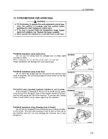
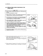
Page 110: ... may cause the machine to lose its balance and turn over so avoid such operations It is particularly dangerous to swing downhill when the bucket is loaded If such operations have to be carried out pile soil to make platform on the slope so that the machine can be kept horizontal when operating Do not travel on slopes of over 30 as there is danger that the machine may overturn 1 2 When traveling do...

Page 111: ...chine travel uphill If engine stops If the engine stops when traveling uphill move the travel levers to the neutral position lower the bucket to the ground stop the machine then start the engine again Precautions on slopes l If the engine stops when the machine is on a slope never use the left work equipment control lever to carry out swing opera tions The upper structure will swing under its own ...

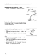
Page 112: ...cket also NOTICE When using the boom or arm to raise the machine always have the bottom of the bucket in contact with the ground Never push with the teeth The angle between the boom and arm should be 90 to 110 The same applies when using the inverting bucket 12 13 2 WHEN BOTH SIDES ARE STUCK When the tracks on both sides are stuck in mud and the machine will not move lay boards as explained above ...

Page 113: ...ange rather than going all the way to the extreme end of the cylinder stroke AE098020 12 14 2 SHOVEL WORK A shovel is suitable for excavating at a position higher than the machine Shovel work is performed by attaching the bucket in the reverse direction AE098040 12 14 3 DITCHING WORK Ditching work can be performed efficiently by attaching a bucket to match the width of the ditch and then setting t...

Page 114: ...T 1 Place the bucket in contact with a flat surface REMARK When removing the pins place the bucket so that it is in light contact with the ground If the bucket is lowered strongly to the ground the resistance will be increased and it will be difficult to remove the pins 2 Remove the stopper bolts and nuts then remove pins and I and remove the bucket NOTICE After removing the pins make sure that th...

Page 115: ...and and remove the bucket NOTICE After removing the pins make sure that they do not become contaminated with sand or mud and that the seals of bushing on both sides do not become damaged 3 4 5 Install the bucket inversely After the bucket is inversed correct the inclination and direction of the retaining pin holes and and stabilize the bucket securely Align the arm with holes and the link with hol...

Page 116: ...an additional safety measure thrust the bucket into the ground Thrust the bucket AE096750 If the control lever is touched by accident the work equipment or the machine may move suddenly and this may lead to a serious accident Before leaving the operator s compartment always set the safety lock lever securely to LOCK position Free b Locko AE096630 1 Put left and right travel levers in the neutral p...

Page 117: ... ground the bottom touches the 4 Set safety lock lever in the LOCK position 12 17 CHECK AFTER FINISHING Check the engine water temperature fuel level on the monitor WORK engine oil pressure and AE098100 Free AE096630 I I a I AE098110 2 73 ...

Page 118: ...part from an emergency In particular if the engine has overheated do not abruptly stop it but run it at medium speed to allow it to cool gradually then stop it 1 Run the engine at low idling speed for about 5 minutes to allow it go gradually cool down 2 Turn the key in starting switch to the OFF position and stop the engine HEAT OFF I 3 Remove the key from starting switch 0 START 2 74 ...

Page 119: ...engine compartment for paper and debris Clean out any paper and debris to avoid a fire hazard 4 Remove any mud stuck to the undercarriage 12 20 LOCKING Always lock the following places 0 Door of operator s cab Always remember to close the window Fuel tank filler port Engine hood Battery box cover Left side door of the machine Hydraulic tank filler port REMARK Use the starting switch key to open an...

Page 120: ...hange direction drive off the ramps and correct the direction then drive on to the ramps again l When turning the machine on the trailer the machine s footing is unstable so carry out the operation slowly l Always check that the door on the cab is locked regardless of whether it is open or closed Do not open or close the door on ramps or on a platform This may cause a sudden change in the operatin...

Page 121: ...on of the ramps lower the work equipment as far as possible without letting it hit the trailer then travel slowly to load or unload the machine When on the ramps do not operate any lever other than the travel lever 6 Load the machine correctly in the specified position on the Front of machine AE081650 OFF canceled trailer REMARK When the work equipment is installed load the machine from the front ...

Page 122: ...about Also hold it down with chains or rope Be particularly careful to ensure that the machine does not slip sideways NOTICE When transporting the machine place rectangular timber under one end of the bucket cylinder to prevent it touching the ground thereby saving it from possible damage AE098150 13 3 PRECAUTIONS FOR TRANSPORTATION g WARNING l Determine the route for transporting the machine by t...

Page 123: ... the right Boom fully raised arm and bucket pulled in fully Face the upper structure straight to the front Idler end Set the safety lock lever to the LOCK position Stop the engine check that the area around the operator s compartment is safe then get off the machine Close the cab door front glass let and right doors and engine hood securely Install shackles to the lifting hooks on top of the boom ...

Page 124: ...e attachments take care not to let dust get into the joints of the piping After removing the attachment plug or tape the joints l After packing check for water leakage and oil leakage Refill if necessary l Fix each section securely to protect cylinders and other parts l Reinstall the pins and bolts which were removed for disassembly l Detachment sites Boom cylinder foot Cylinders and associated pi...

Page 125: ...4 81 9n 5 90x 3 23 x 3 44 SS Snf Weight 3 3 ton Capacity 4 9 x 1 94 x 1 57 14 9ms I Weight 3 3 ton Capacity 6 36xl 17x1 57 11 7ma _ p z E Weight 4 7 ton Capacity 7 29 x 1 62 x 0 78 9 2d Weight 2 0 ton 1 Capacity 4 62 x 0 91 x 0 57 2 4mS Weight 1 3 ton Capacity 2 03 x 1 17 x 1 57 3 7m5 Weight 8 5 ton Capacity 2 96 x 1 18x 0 76 2 n 2 81 ...

Page 126: ... 61 9d 15 90 x 3 23 x 3 34 63 7n1 1 Weight 3 8 ton Capacity 4 9 x 1 94 x 1 57 14 9m Weight 3 8 ton Capacity 6 36 x 1 17 x 1 57 11 7mJ _ Weight 4 7 ton Capacity 7 29 x 1 62 x 0 78 9 2d mgg Capacity 4 62 x 0 91 x 0 57 q 2 4m Weight 1 7 ton Capacity 2 03 x 1 17 x 1 57 3 7ma I WeigM 6 5 ton Capacity 2 96x1 18x0 76 2 i XOW032 2 81 l ...

Page 127: ... 3 13 59 7d P F s FY Weight 3 8 ton 1 Capacity 4 9 x 1 94 x 1 57 q 14 9m5 Weight 3 8 ton Capacity 6 36 x 1 17 x 1 57 11 7ma Weight 4 7 ton Capacity 7 29 x 1 62 x 0 78 9 2m9 4620 wei Capacity 4 62 x 0 91 x 0 57 2 4ma Weight 1 7 ton Capacity 2 03 x 1 17 x 1 57 3 7ma Weight 8 5 ton Capacity 2 96x1 18xO 76 2 8m 2 W 2 ...

Page 128: ...e is at a right angle to the tracks Then jack up the track frame making use of the work equip ment Put the block 20 to 30 cm 8 to 12 in square from outside of track frame Using the boom cylinder slowly lower the machine until the track frame reaches the stoppers Lower the machine carefully and install bolts 0 one side front rear 8 bolts out of bolts 0 Tightening torque 1715 f 200 Nm 175 20 kgm 127...

Page 129: ... 2 in Take care not to raise the track frame so much that the stopper bolt is distorted Pull the machine forward with the arm and the track frame will slide sideways I Extend the track frame until it comes into contact with the stopper then lower the machine slowly to the ground Install bolts one side front rear 22 and tighten to specified torque Tightening torque 2750 k 300 Nm 280 30 kgm 2025 f 2...

Page 130: ... mix one antifreeze with a different brand For details of the antifreeze mixture when changing the coolant see 24 2 WHEN REQUIRED Use a Permanent Antifreeze ethylene glycol mixed with corro sion inhibitor antifoam agent etc meeting the standard require ments as shown below With permanent antifreeze no change of coolant is required for a year If it is doubtful that an available antifreeze meets the...

Page 131: ...tery charge as close as possible to lOO and insulate it against cold temperature so that the machine can be started easily the next morning REMARK Measure the specific gravity and calculate the rate of charge from the following conversion table 20 C 0 C 10 C 20 C 100 1 28 1 29 1 30 1 31 90 1 26 1 27 1 28 1 29 80 1 24 1 25 1 26 1 27 75 1 23 1 24 1 25 1 26 14 1 4 PREPARING THE CAB HEATER If the ambi...

Page 132: ... low idle and bring work equipment beside track 2 Slightly float track by slowly pushing the ground and cause track to idle run Perform this for the opposite track too l As the battery capacity drops markedly in low temperatures cover the battery or remove it from the machine keep it in a warm place and install it again the next morning l If electrolyte level is found low add distilled water in th...

Page 133: ... danger and cover it with canvas etc AE099270 l Completely fill the fuel tank lubricate and change the oil before storage l Apply a thin coat of grease to metal surface of the hydraulic piston rods l Disconnect the negative terminals of the battery and cover it or remove it from the machine and store it separately l If the ambient temperature is expected to drop below O C always add antifreeze to ...

Page 134: ...AFTER STORAGE NOTICE If the machine is stored without carrying out the monthly rust prevention operation request your Komatsu distributor for service Carry out the following procedure when taking the machine out of long term storage l Wipe off the grease from the hydraulic cylinder rods l Add oil and grease to all places 15 4 Wl l MACHINE AFTER LONG TERM When starting the machine after a long term...

Page 135: ...ope that has ample strength for the weight of the machine that is being towed If the machine sinks in mud and cannot get out under its own power or if the drawbar pull of the excavator is being used to tow a heavy object use a wire rope as shown in the diagram on the right Place pieces of wood between wire ropes and body to prevent damage to ropes and body At this time never use the hole for light...

Page 136: ...ks Battery electrolyte is dilute sulphuric acid and it will attack your clothes and skin If it gets on your clothes or on your skin wash it immediately off with large amounts of water If it gets in your eyes wash it out with fresh water and consult a doctor When handling battery always wear protective goggles When removing the battery first disconnect the cable from the ground normally from the ne...

Page 137: ...jury Make sure that there is no mistake in the booster cable connections The final connection is to the revolving frame but sparks will be generated when this is done so connect to a place as far as possible from the battery However avoid connecting the cable to the work equipment as conduction is poor Use care when removing the cables from the machine that has been started Do not allow the cable ...

Page 138: ...lem machine AD052e80 Connect the other clip of booster cable to the positive terminal of the normal machine Connect one clip of booster cable to the negative terminal of the normal machine Connect the other clip of booster cable to the engine block of the problem machine Starting the engine 1 Make sure the clips are firmly connected to the battery terminals 2 Start the engine of the normal machine...

Page 139: ... booster cable from the engine block of the problem machine Remove the other clip of booster cable from the negative 0 terminal of the normal machine Remove one clip of booster cable from the positive terminal of the normal machine Engine block of the problem machine AD05298 Remove the other clip of booster cable from the positive terminal of the problem machine 2 93 ...

Page 140: ... l Insufficient battery charge l Defective starting motor l Defective safety relay Pinion of starting motor keeps going in and out l Charge o Replace l Insufficient battery charge l Defective safety relay l Insufficient battery charge l Defective starting motor Starting motor turns engine sluggishly l Charge o Replace a Defective wiring l Insufficient battery charge o Check repair l Charge Startin...

Page 141: ...wear of sprocket Bucket rises slowly does not rise Main causes l Lack of hydraulic oil l Clogged element in hydraulic tank strainer l Loose fan belt l Dirty oil cooler l Lack of hydraulic oil l Track too loose l Lack of hydraulic oil Remedy l Add oil to specified level see CHECK BEFORE STARTING l Clean see EVERY 2000 HOURS SERVICE l Adjust fan belt tension see EVERY 250 HOURS SERVICE l Clean see E...

Page 142: ...r fin or damaged fin Defective thermostat Loose radiator filler cap high altitude operation Defective water level sensor Lack of fuel Air in fuel system Defective fuel injection pump or nozzle Starting motor cranks engine sluggishly Preheating monitor does not light up Defective compression o Defective valve clearance Remedy l Add oil to specified level see CHECK BEFORE STARTING l Replace cartridg...

Page 143: ...le o See defective compression above l Defective turbocharger l Clean or replace turbocharger Combustion noise occasionally makes breathing sound Abnormal noise generated combustion or mechanical l Defective nozzle a Low grade fuel being used l Overheating l Damage inside muffler l Excessive valve clearance Remedy l Add oil to specified level see CHECK BEFORE STARTING o Replace nozzle l Change to ...

Page 144: ...ht up there is probably a broken bulb or disconnection in the monitor so ask your Komatsu distributor to inspect it Park the machine on level ground and check the monitor lamps ENGINE THROTTLE CONTROLLER AND PUMP CONTROLLER If any abnormality occurs the abnormality is indicated by the lamp and an 8 digit code Check the content of the display and contact your Komatsu distributor for repairs Pump co...

Page 145: ...MAINTENANCE A WARNING Before carrying out maintenance always attach the WARNING TAG to the control lever in the operator s cab 3 l ...

Page 146: ...d grease Keeping the machine clean Always keep the machine clean This makes is easier to find parts causing problems Keep in particular grease fittings breathers and oil level gauges clean and avoid foreign matters from getting in them Be careful of hot water and oil Draining hot oils and coolants and removing their filters immediately after the engine stops are hazardous Allow the engine to cool ...

Page 147: ...leaner or light oil for cleaning parts Keep flame or cigarette light away from light oil Clamp faces When O rings or gaskets are removed clean the clamp faces and replace the O rings and gaskets with new ones Be sure to fit O rings and gaskets when assembling Objects in your pockets Keep your pockets free of loose objects which can fall out and drop into the machinery especially when you work on t...

Page 148: ...ng at dusty worksites do as follows l Inspect the air cleaner clogging monitor to see whether the air cleaner is blocked up Clean the air cleaner at shorter intervals than specified l Clean the radiator core frequently to avoid clogging l Clean and replace the fuel filter frequently l Clean electrical components especially the starting motor and alternator to avoid accumulation of dust Avoid mixin...

Page 149: ...al Even if the oil is not dirty always replace the oil after the specified interval Oil corresponds to blood in the human body so always be careful when handling it to prevent any impurities water metal particles dirt etc from getting in The majority of problems with machine are caused by the entry of such impurities Take particular care not to let any impurities get in when storing or adding oil ...

Page 150: ...ge amounts of calcium and other impurities so if it is used scale will stick to the engine and radiator and this will cause defective heat exchange and overheating Do not use water that is not suitable for drinking When using anti freeze always observe the precautions given in the Operation and Maintenance Manual Komatsu machines are supplied with Komatsu original anti freeze in the coolant when t...

Page 151: ...m with a waterproof sheet or take other measures to protect them l To prevent any change in quality during long term storage be sure to use in the order of first in first out use the oldest oil or fuel first 18 1 6 FILTERS l Filters are extremely important safety parts They prevent impurities in the fuel and air circuits from entering important equipment and causing problems Replace all filters pe...

Page 152: ... other than these specified by Komatsu Be careful to keep the electric system free of water when washing the machine or when it rains Since the controller for the control system may cause malfunction due to external wave interference before installing a radio receiver and a walkie talkie or citizen band consult your Komatsu distributor When working on the seashore carefully clean the electric syst...

Page 153: ...der internal pressure so when loosening the plug or screw or the hose joint do not stand in front of the part Loosen it slowly to release the internal pressure before removing it o When carrying out inspection or maintenance of the hydraulic circuit always bleed the air form the hydraulic tank to remove the internal pressure Periodic maintenance includes the inspection of the hydraulic oil level r...

Page 154: ... of their travel within 5 6 seconds of stopping the engine Remove the cap from the hydraulic tank Start the engine run for approx IO seconds then stop the engine Do not run the engine at above 1000 rpm Place the work equipment levers at neutral Operate all the work equipment levers to the end of their travel within 5 6 seconds of stopping the engine Repeat Steps 4 5 three times 18 4 2 RELEASING PR...

Page 155: ... swing motor piping l Replace travel motor swivel l Remove travel motor swivel Dioina 0 l O l O 0 o o 1 Bleed the air from the swing motor and travel motor only when the oil inside the motor case has been drained a 1 2 l 0 b Bleeding air from pump Loosen the bleeder at portion remove plug I then add oil through filler to fill the pump with oil After completion of bleeding the air install plug firs...

Page 156: ... swing Run the engine at low idling and swing 2 or more times slowly and uniformly to the left and right If the air is not bled from the swing motor the bearings of the motor may be damaged AE098360 7 procedure on both the left and right sides and rotate the track equally both forward and in reverse Start operations After completion of bleeding the air stop the engine and wait for at least 5 minut...

Page 157: ...arts in parentheses are to be replaced at the same time Item Part No Part Name Replacement frequency Hydraulic oil filter 07063 01142 07000 05180 Element O ring Every 250 hours service Engine oil filter Hydraulic tank breather 600 211 1230 Cartridge 2OY 60 21410 Element 2OY 60 21420 Seal washer 1 Every 250 hours service Every 250 hours service Fuel filter 600 311 8292 Cartridge I I 1 Every 500 hou...

Page 158: ...0 I 4152 09244 03036 208 70 34160 208 70 34170 198 32 14210 198 32 11221 Vartical pin type Tooth Pin Lock Horizontal pin type Tooth Pin Cutter left Cutter right Bolt Nut 5 5 5 5 5 1 Gr 8 Wear limit of bucket tooth I Wear limit I Vertical type 0 160 mm 6 3 in I I AE098390 Horizontal type 0 130 mm 5 1 in I I AE098400 3 14 ...

Page 159: ... OF FLUID Engine oil Water 2 3 AMBIENT TEMPERATURE 2 4 14 32 50 68 86 104 122 F 0 20 10 0 10 20 30 40 50 C 4dd antifreeze 1 CAPACITY Specified Refill 38 32 t 10 0US gal 8 5US gal 8 4UK gal 7 0UK gal 24 e 6 3US gal 5 3UK gal 11 5e 3 0US gal 2 5UK gal 1 07e 3 28US gal 3 24UK gal 46Ot 255 t 121 5 US gal 7 4US gal 101 2 UK gal j6 1UK gal 550 e 145 US gal 121 UK gal 34 e 9 0US gal 7 5 UK gal 22 e 5 8US...

Page 160: ... temperature goes up to 70 C 50 F more or less in the day time l Use API classification CF 4 or CG 4 engine oil and if using API classification CD reduce the engine oil change interval to half l There is no problem if single grade oil is mixed with multigrade oil SAE lOW 30 15W 40 but be sure to add single grade oil that matches the temperature in the table l We recommend genuine Komatsu Dresser C...

Page 161: ...3 17 ...

Page 162: ...MEMORANDA 3 18 ...

Page 163: ...3641 09021 03044 09007 00836 07952 80002 For greasing work 07951 I 1400 07950 90403 09039 00150 09055 I 0390 09024 00300 Remarks Applicable width across flats SI SZ 14mm 17mm 19mm 22mm 24mm 27mm dI s2 30mm 32mm Am53370 Interchangeable flat head and cross head type Applicable width across flats IO mm 13 mm 14 mm 17 mm 19 mm 22 mm 24 mm Extension Handle Applicable width across flats 36 mm 41 mm Appl...

Page 164: ... b 1 7 kgm 9 300 9 73 k 1 03 23 2 2 1 48 5f 5 0 82 6f 7 2 131 f 14 6 10 13 2k 1 4 1 35 0 15 8 13 31 4f 2 9 3 2 f 0 3 IO 17 65 7 6 8 6 7f 0 7 12 19 112 f 9 8 11 5 1 0 14 22 177 19 18 0i 2 0 16 24 279 29 28 5 5 3 206f 21 18 27 383 39 39 3 282 f 29 20 30 549 58 56 6 405 f 43 22 32 746 k 78 76 8 549 f 58 24 36 927 98 94 5 5 10 684f72 27 41 1320 140 135 15 973 f 100 30 46 1720 190 175 5 20 1270f 140 33...

Page 165: ... it is difficult to judge the condition of the parts simply by periodic maintenance so they should always be replaced after a fixed time has passed regardless of their condition This is necessary to ensure that they always maintain their function completely However if these parts show any abnormality before the replacement interval has passed they should be repaired or replaced immediately If the ...

Page 166: ...ose nozzle injection pump 1 4 1 Spill hose between nozzles I I 5 5 Turbocharger lubricating hose 1 Every 2 years or 4000 hours 6 Front pump hose front pump line filter 1 whichever comes sooner 7 Front pump hose line filter control valve 1 8 Rear pump hose rear pump line filter 1 9 IR ear pump hose line filter control valve __TIPi 10 Front and rear pump branch hoses 2 11 Seat belt 1 Replace every 3...

Page 167: ...eater 3 36 Replace bucket teeth vertical pin type 3 37 Replace bucket teeth horizontal pin type 3 40 Adjust bucket clearance 3 41 Clean line filter 3 42 Drain water from water separator 3 42 CHECK BEFORE STARTING Check coolant level add water Check oil level in engine oil pan add oil 3 43 3 43 Check fuel level add fuel 3 44 Check oil level in hydraulic tank add oil 3 45 Check dust indicator 3 46 C...

Page 168: ... 1 point 3 49 Check oil level in swing machinery case add oil 3 50 Drain water and sediment from fuel tank 3 50 EVERY 250 HOURS SERVICE Check oil level in final drive case add oil Check level of battery electrolyte 3 52 Change oil in engine oil pan replace engine oil filter cartridge 3 53 Replace hydraulic filter element 3 54 Lubricate swing circle 3 points 3 55 Check fan belt tension adjust 3 56 ...

Page 169: ... 23 2 MAINTENANCE INTERVAL WHEN USING HYDRAULIC BREAKER For machines equipped with a hydraulic breaker the hydraulic oil deteriorates faster than for normal bucket digging operations so set the maintenance intervals as follows l Replacing hydraulic element On new machines replace the element after the first 100 to 150 hours then carry out further replacement of the element accord ing to the table ...

Page 170: ...Carry out the following maintenance only after the first 250 hours l REPLACE FUEL FILTER CARTRIDGE l CHECK ENGINE VALVE CLEARANCE ADJUST For details of the method of replacing or maintaining see the section on EVERY 500 HOURS and 2000 HOURS SERVICE 3 26 ...

Page 171: ...ear end of the air cleaner with a clean cloth and adhesive tape Clean the air cleaner body interior and the cover Direct dry compressd air less than 700 kPa 7 kg cm2 100 psi AE098450 to element from inside along its folds then direct it from outside along its folds and again from inside 1 2 31 4 Remove one seal from the outer element whenever the outer element has been cleaned Replace the outer el...

Page 172: ...or valve and clean with compressed air After cleaning install it I AE083060 Replacing element 1 First remove the outer element and then remove the inner element 2 Place the cover over the air intake part to prevent dust entering 3 Clean the air cleaner body interior then remove the cover from the air intake port 4 Fit a new inner element and tighten it with nuts 5 Install the outer element Push th...

Page 173: ...ith your hand Remove the filler cap slowly to allow pressure to be relieved l Clean the inside of the cooling system change the coolant and replace the corrosion resistor according to the table below Kind of coolant Cleaning inside of cooling system and changing coolant Replacing corrosion resistor Permanent type antifreeze All season type Every year autumn or every 2000 hours whichever comes firs...

Page 174: ...ixing rate of water and antifreeze Min atmospheric temperature Amount of antifreeze Amount of water AWARNING Antifreeze is flammable so keep it away from any flame l Use city water for the cooling water If river water well water or other such water supply must be used contact your Komatsu distributor l We recommend use of an antifreeze density gauge to control the mixing proportions AWARNING When ...

Page 175: ...hat the radiator is always full While flushing water through the system watch carefully that the water inlet hose does not come out of the radiator water filler After flushing stop the engine open drain valve and drain plug 0 then close it again after all the water has drained out A AE0984 80 After draining the water clean with a flushing agent We recommend use of a Komatsu genuine cleaning agent ...

Page 176: ...RVICE Install the undercover Add cooling water until it overflows from the water filler To remove the air in the cooling water run for five minutes at low idling then for another five minutes at high idling When doing this leave radiator cap off After draining off the cooling water of reserve tank 0 clean the inside of the reserve tank and refill the water between FULL and LOW level Stop the engin...

Page 177: ...First tighten to a tightening torque of 390 40 Nm 40 4 kgm 290 30 lb ft then check that the nut and shoe are in close contact with the link contact surface 2 After checking tighten a further 120 f 10 Order for tightening Tighten the bolts in the order shown in the diagram on the right After tightening checkthat the nut and shoe are in close contact with the link mating surface I AD053090 3 33 ...

Page 178: ...ally inspect the track tension so as to maintain the stand ard tension Carry out the check and adjustment under the same conditions as when operating on job sites where the track becomes clogged with mud measure with the track clogged with mud Inspection 1 Raise the chassis with the boom and arm When doing this operate the levers slowly 2 Measure the clearance between the bottom of the track frame...

Page 179: ...in front of the plug 0 If the track tension is not relieved by this procedure please contact your Komatsu distributor When increasing tension Prepare a grease gun Pump in grease through grease fitting with a grease gun To check that the correct tension has been achieved move the machine backwards and forwards Check the track tension again and if the tension is not correct adjust it again Continue ...

Page 180: ... out smoothly move the machine backwards and forwards a short distance 4 5 Tighten plug 0 To check that the correct tension has been achieved move the machine backwards and forwards 6 Check the track tension again and if the tension is not correct adjust it again 24 2 5 CHECK ELECTRICAL INTAKE AIR HEATER Before the start of the cold season once a year contact your Komatsu distributor to have the e...

Page 181: ...evers within 15 seconds after stopping the engine After confirming that the work equipment is in a stable condition lock the safety lock lever Set so that the bottom face of the bucket is horizontal Use a hammer and drift to knock out lock pin If the drift is set against rubber pin lock when it is hit the rubber pin lock may break Set it against the back of the pin After removing lock pin and rubb...

Page 182: ... pin lock into the hole of the adapter When doing this be careful that the rubber pin lock does not fly out from the adapter surface 6 Clean the inside of point 0 then install it to adapter 0 If there is mud stuck to it or if there are protrusions the point will not enter the adapter properly and there will not be proper contact at the mating portion I AE083230 1 7 Fit point to adapter 0 and confi...

Page 183: ...th always check the following I After the lock pin has been knocked in completely check that it is being secured by the point and surface 2 Lightly hit lock pin in the reverse direction from which it was hit in 3 Lightly hit the tip of the point from above and below and hit its sides from right and left AE083250 4 Confirm that rubber pin lock and lock pin are set as shown in the figure The life of...

Page 184: ... out with a hammer Carry out full stroke operation of the control levers within 15 seconds after the engine has stopped After confirming that the work equipment is in a stable condition lock the safety lock lever Set so that the bottom face of the bucket is horizontal 2 Place a bar on the pin head and strike the bar with a hammer to knock out pin 0 Remove tooth 0 REMARK Use a round bar with a smal...

Page 185: ...e amount of play a Measurement is easier of you move the bucket to one side or the other so all the play can be measured in one place Use a gap clearance gauge for easy and accurate measure ment Loosen the four bolts bolt and plate 0 Remove shim corresponding to the amount of play a measured above Example In the case of play of 3 mm remove two 1 0 mm shims and one 0 5 mm shim Play becomes 0 5 mm F...

Page 186: ...in case 0 to install it Replace O ring and backup ring as a set when reassembling Tinhteninn toraue Case 0 440 f 5 Nm 4 5 f 0 5 kgm 32 5 f 3 6 Ibft After reassembling the line filter bleed the air from the circuit For details see 18 5 BLEEDING AIR FROM CIRCUIT AE098580 AE098590 24 2 10 DRAIN WATER FROM WATER SEPARATOR When float is at or above red line 0 drain the water according to the following ...

Page 187: ...wn in the diagram on the right If the water level is low add water through the water filler of reserve tank and radiator filler to the FULL level After adding water tighten the caps securely 24 3 2 CHECK OIL LEVEL IN ENGINE OIL PAN ADD OIL 1 Open the rear cover on the machine 2 Remove dipstick and wipe the oil off with a cloth 3 Insert dipstick fully in the oil filler pipe then take it out again 4...

Page 188: ...RNING When adding fuel never let the fuel overflow This may cause a fire If you spill fuel thoroughly clean up any spillage 1 2 Use sight gauge on the front face of the fuel tank to check that the tank is full If the fuel level is not within the sight gauge add fuel through filler port 0 while watching sight gauge Fuel capacity 550 e 145 US gal 121 UK gal For details of the fuel to use see 20 USE ...

Page 189: ...engine move each control r AH82200 lever for work equipment and travel to the full stroke in all directions to release the internal pressure the machine II Iloo Forward of Check sight gauge 0 The oil level is normal if between the H and L marks NOTICE Do not add oil if the level is above the H line This will damage the hydraulic equipment and cause the oil to spurt out 4 If the level is below the ...

Page 190: ...f the fuse and any sign of disconnection or short circuit in the electric wiring Check also for loose terminals and tighten any loose parts Check the following points carefully l Battery 0 Starting motor l Alternator Please contact your Komatsu distributor for investigation and correction of the cause a WARNING Accumulation of flammable material dead leaves twigs grass etc around the battery may c...

Page 191: ...as pushed out AEO97540 24 3 8 CHECK FOR WATER AND SEDIMENT IN WATER SEPARATOR DRAIN WATER The water separator separates water mixed in the fuel If float is at or above red line 0 drain the water according to the following procedure 1 Loosen drain plug and drain the accumulated water until the float reaches the bottom 2 Tighten drain plug 0 3 If the air is sucked into fuel line when draining and wa...

Page 192: ... greasing posture below then lower the work equipment to the ground and stop the engine 2 Using a grease pump pump in grease through the grease fittings shown by arrows 3 After greasing wipe off any old grease that was pushed out AE098610 2 Boom foot pin 2 points 1 Boom cylinder foot pin 2 points 3 48 ...

Page 193: ... Arm coupling pin Ipoint 6 Arm cylinder rod end 1 point 7 Bucket cylinder foot pin I point 8 Arm Link coupling pin I point 9 Arm Bucket coupling pin I point IO Link coupling pin 2 points 11 Bucket cylinder rod end I point 12 Bucket Link coupling pin 1 point AE098640 AE096670 I 11 AE098680 3 49 ...

Page 194: ...of the oil to use see 20 USE OF FUEL COOLANT AND LUBRICANTS ACCORDING TO AMBIENT TEMPERATURE 5 If the oil level exceeds the H mark on the dipstick loosen drain valve to drain the excess oil 6 After checking oil level or adding oil insert the dipstick into the hole and install air bleeding plug 0 24 4 3 DRAIN WATER AND SEDIMENT FROM FUEL TANK 1 Carry out this procedure before operating the machine ...

Page 195: ...mark and pluo I perpendicular to the ground surface _ 2 Remove plug 0 using the handle When the oil level reaches a point 10 mm below the bottom of the plug hole the correct amount of oil has been added 3 If the oil level is too low install plug 0 operate the travel levers and drive forward or in reverse to rotate the sprocket one turn AE098710 Then repeat Step 2 to check again 4 If the oil level ...

Page 196: ...ctrolyte is at the specified level IO to 12 mm 0 40 to 0 47 in above the plate If the electrolyte level is low add distilled water to the specified level If the battery electrolyte is spilled have dilute sulphuric acid added 3 Clean the air hole in the battery cap then tighten the cap securely When adding distilled water in cold weather add it before starting operations in the morning to prevent t...

Page 197: ... if there are excessive metal particles or foreign material please contact your Komatsu distributor 4 5 Install drain valve 8 Open the engine hood Using the filter wrench from the upper side of the engine turn filter cartridge counterclockwise to remove it In particular if this operation is carried out immediately after stopping the engine a large amount of oil will come out so wait for 10 minutes...

Page 198: ...erated for 6 months the oil and filter cartridge must be replaced when the machine has been operated for 250 hours 24 5 4 REPLACE HYDRAULIC FILTER ELEMENT 1 Remove the cap from oil filler 0 and release the internal pressure 2 Loosen 4 bolts then remove cover 0 When doing this the cover may fly out under the force of spring 0 so hold the cover down when removing the bolts Tightening torque 95 6 5 1...

Page 199: ... element replacement should be at 100 to 150 hours for 8 Xe new machines Thereafter replace the element according to the 8 c Replacement interval for main filter table on the right d Replacement interval for extra filter Replace the additional filter element for the breaker every approx 250 hours when breaker operating ratio is more than 50 accord 1000 ing to the table on the right See 23 2 MAINTE...

Page 200: ...x 6 kg 13 lb When adjusting the V belt do not attempt to push alternator directly with a bar or the like but use a wood pad to prevent damage to the core Fanpully 6 7mm 0 23 0 26 in _ FEY Alternator Crankshaft pully AD098800 3 Tighten the bolts and nuts and to fix alternator in position 4 Check each pulley for damage wear of the V groove and wear of the V belt In particular be sure to check that t...

Page 201: ...n only clean fuel comes out close drain plug 24 5 8 REPLACE HYDRAULIC TANK BREATHER ELEMENT 1 Insert key in cap 0 then turn the key counterclockwise to release the lock 2 3 Push cap down to release the pressure inside the tank Keep cap pushed down turn counterclockwise and remove cap 0 4 5 6 Remove ring GJ and take out the element Install new element with ring 0 After installing the element push c...

Page 202: ...clockwise to remove it 3 Clean the filter holder fill a new filter cartridge with clean fuel coat the packing surface with engine oil then install it to the filter holder 4 When installing tighten until the packing surface contacts the seal surface of the filter holder then tighten it up l 2 to 3 4 of a turn If the filter cartridge is tightened too far the packing will be damaged and this will lea...

Page 203: ... surface for damage or foreign material If any damage or foreign material is found in the packing replace the packing with a new part then repeat Steps 3 6 to install the filter cartridge NOTICE When the engine has run out of fuel carry out the same procedure and crank the engine for 15 20 seconds Repeat this operation 2 3 times to bleed the air Do not rotate the starting motor continuously for mo...

Page 204: ... the grease and check that the height of the grease in the portion where the pinion passes is at least 25 mm 1 0 in Add more grease if necessary Check if the grease is milky white If it is milky white it is necessary to change the grease Please contact your Komatsu distributor The total amount of grease is 35 e 31 5 kg 9 2 US gal 7 7 UK galL77 2 lb 4 Install cover with bolts 0 3 60 ...

Page 205: ...fins oil cooler fins using compressed air At the same time clean the net in front of the oil cooler Steam or water may be used instead of compressed air Check the rubber hose Replace with a new one if the hose is found to have cracks or to be hardened by ageing Further check hose clamps for looseness NOTICE To prevent damage to the fins apply compressed air from and appropriate distance Damaged fi...

Page 206: ...ool down before carrying Container to catch drained oil Min 22 capacity Refill capacity 22 5 8 US gal 4 8 UK gal Set an oil container under drain valve under the machine body Loosen drain valve under the body drain the oil then tighten the drain valve again Remove bleeding plug 0 Add the specified amout of engine oil through gauge hole 0 For details of the oil to use see 20 USE OF FUEL COOLANT AND...

Page 207: ...il level If the oil is up to near the bottom of the plug hole it is normal If insufficient remove plug and add oil through the hole of plug up to the bottom of the plug hole 0 For details of the oil to use see 20 USE OF FUEL COOLANT AND LUBRICANTS ACCORDING TO AMBIENT TEMPERATURE NOTICE If excess oil is supplied drain it to the specified amount to avoid overheating 3 Install plugs and 0 4 Close th...

Page 208: ...he new cartridge with engine oil then install it to the filter holder I 5 When installing tighten until the packing surface contacts the seal surface of the filter holder then tighten it up 2 3 of a turn If the filter cartridge is tightened too far the packing will be damaged and this will lead to leakage of coolant If the filter cartridge is too loose coolant will also leak from the packing so al...

Page 209: ... DRIVE CASE AWARNING l The oil is at high temperature immediately after the machine has been operated Wait for the oil to cool down before carrying out maintenance l If there is still pressure remaining inside the case the oil or plug may fly out Loosen the plug slowly to release the pressure AE098710 REMARK Check the O rings in the plugs for damage If necessary replace with new ones 4 Screw in pl...

Page 210: ...rm and bucket cylinders to the stroke end then lower the boom and put the bucket teeth in contact with the ground Lock the safety lock lever and stop the engine Remove the cap of oil filler 0 I AE082200 Set the oil container under the drain plug under the machine Remove drain plug and drain the oil Check the O ring installed to plug 8 and if it is damaged replace the O ring After draining the oil ...

Page 211: ...ap down and turn the cap clockwise Turn key clockwise to lock the cap then remove key 0 For type of oil to be used see 20 USE OF FUEL COOLANT AND LUBRICANTS ACCORDING TO AMBIENT TEMPERATURE NOTICE When the hydraulic breaker is installed the hydraulic oil dete riorates earlier than in normal bucket digging work Therefore replace the hydraulic oil according to the chart at the right 9 After replacin...

Page 212: ...p and remove the hose Clean the breather body with light oil or Remove breather 0 cleaning oil Replace O ring with new one Coat a new O ring with engine oil set it then install breather 0 Check the breather hose If caked oil sludge adheres to the inside replace the hose with a new one 3 68 ...

Page 213: ...spection or repair If the engine is started frequently carry out inspection every 1000 hours 24 8 6 CHECK ENGINE VALVE CLEARANCE ADJUST As special tool is required for removing and adjusting the parts you shall request Komatsu distributor for service 24 8 7 CHECK VIBRATION DAMPER Check that there are no cracks or peeling in the outside surface of the rubber If any cracks or peeling are found conta...

Page 214: ...0 250 500 1000 and 2000 hours should be carried out at the same time 24 9 1 CHECK WATER PUMP Check that there is oil leakage water leakage or clogging of the drain hole If any abnormality is found contact your Komatsu distributor for disassembly and repair or replacement 3 70 ...

Page 215: ...SPECIFICATIONS 4 1 ...

Page 216: ... l Travel speed Standard bucket With side cutter Low speed High speeed 1 425 mm 56 1 in 1 550 mm 61 0 in 5 5 km h 12 3 MPH 3 1 km h 6 9 MPH l Swing speed 9 3 rpm TRACK SHOE l Triple grouser shoe standard I 600 mm 23 6 in width 700 mm 27 6 in width ENGINE l Model Komatsu S6D125 IVV diesel engine l Flywheel horsepower 0 Starting motor 206 kW 276 1 HP 2000 rpm 24 V 7 5 kW l Alternator I 24 V 25 A l B...

Page 217: ...ndard bucket With side cutters l Travel speed Low speed High speed l Swing speed TRACK SHOE 0 Triple grouser shoe standard ENGINE l Model 0 Flywheel horsepower 0 Starting motor 0 Alternator 1 8m3 2 08 cu yd l 6 m3 1 425 mm 56 1 in 1 550 mm 61 0 in 3 1 km h 6 9 MPH 5 5 km h 12 3 MPH 9 3 rpm 600mm 23 6 in width 700mm 27 6 in width Komatsu S6Dl25 W diesel engine 206 kW 276 1 HP 2000 rpm 24 V 7 5 kW 2...

Page 218: ...ucket With side cutters 1 425 mm 56 1 in 1 550 mm 61 O in l Travel speed 0 Swing speed Low speed High speed 3 1 km h 6 9 MPH 5 5 km h 12 3 MPH 9 3 rpm TRACK SHOE l Triple grouser shoe standard ENGINE l Model l Flywheel horsepower 0 Starting motor 0 Alternator 700mm 27 6 in width 750mm 29 5 in width Komatsu S6D125 W diesel engine 206 kW 276 1 HP 2000 rpm 24 V 7 5 kW 24 V 25 A l Battery 12V150Ahx2pi...

Page 219: ...5 SPECIFICATIONS PC400 PWOOLC 5 EXCEPT MIGHTY AND HD The values given are the values for PC4006 1 Values for PC4OOLC 5 In cases where there are no values given in 1 the values are the same as for PC400 5 ...

Page 220: ...EXCEPT MIGHTY AND HD 1 2 The mark s indicates the dimensions for shovel operation Never allow other person than the operator to enter the swing range Max swing range Max digging radius 1181008 9 11995W4 12020 39 5 12195 407 x0222035 4 4 ...

Page 221: ...OPTIONS ATTACHMENTS n 5 l ...

Page 222: ...n the operation is carried out by two or more workers determine signals and follow these during the operation When carrying heavy objects more than 25 kg 55 lb use a crane When removing heavy parts always support the part before removing it When lifting such heavy parts with a crane always pay careful attention to the position of the center of gravity It is dangerous to carry out operations with t...

Page 223: ...e control levers to stop the swing to the point where the upper structure stops completely so there is danger of mistaking the distance and hitting something Always operate so that there is an ample margin to the stopping point Furthermore the hydraulic drift also becomes larger when the work equipment is stopped in mid air it will gradually move down under its own weight Always follow the correct...

Page 224: ...ed and use the lifting operation mode Depending on the posture of the work equipment there is danger that the wire or load may slip off the hook Always be careful to maintain the correct hook angle to prevent this from happening Never steer the machine while lifting a load If the bucket with hook is turned and used for operations it will hit the arm during dumping operations so be careful when usi...

Page 225: ...g it Adjust the lengths of the belt on both the buckle and the tongue sides so that the buckle is located at the mid point of your body front Adjust the seat so that the operator still feels that there is sufficient knee room when fully depressing the pedal while seated with operator s back against the backrest For suspension type seat adjust belt after adjusting the seat position After adjusting ...

Page 226: ...e belt Pull the belt while holding it at a right angle to buckle or tongue Inspect bolts and fittings on the chassis for tightness Retighten any loose bolts to 20 29 Nm 2 3 kgm 15 20 Ibft torque If the seat is scratched or frayed or if any of the fittings are broken or deformed from long service replace the seat belt immediately 0 wAE078100 5 6 ...

Page 227: ...erature enough to feel cool when entering the cab AE099060 29 2 CHECKING AND MAINTAINING CAR COOLER Checking coolant level If the cooling effect is poor check the side glass liquid eye of the receiver drier If there are many bubbles the coolant level is too low Check whether there is any coolant and have the cooler serviced Clogging of condenser 14 16mm 0 55 0 63 in Checking and adjusting V belt t...

Page 228: ...will be closed and heating function will stop Blower switch Used for both controlling the air flow in cooling and heating and as the main switch Changeable at three steps low medium and high Placing knob in OFF cuts off the power supply and stops the air conditioner Cooler temperature knob The temperature is controlled with this knob for cooling It is also the cooler switch Move the knob towards L...

Page 229: ...in to the feet Outlet change over knob 0 FOOT Heater temperature knob 0 See table below Blower switch 0 See table below Cooler temperature knob 0 OFF x HeFzF P Blower switch I Quick heating HIGH HIGH Normal heating MEDIUM MEDIUM or LOW Mild heating I I LOW LOW Dehumidity and heating Set the knobs to the following positions and a dry fresh warm breeze will be flowed from the vents at operator s fee...

Page 230: ... stopped o If hot water is circulating in the heater it is like having a hot heater it is like having a hot water bottle in the cab Always make sure the heater temperature knob is at the OFF position o When not using the heater for a long period fully close the hot water outlet and inlet valves under the engine water manifold and radiator l Be careful not to overcool the cab The cab should feel co...

Page 231: ...r is colorless and odorless and However if it gets in the eyes or on the hands it will be cause of frostbite or loss of sight so never loosen any part of the refrigerant circuit Check during off season When the air conditioner is not being used run the compressor at low speed for a few minutes every week to avoid loss of oil Run the engine at low speed with the cooler temperature regulator knob at...

Page 232: ...reaker is installed l When the front part of the pedal is depressed the breaker is actuated l The lock pin actuates locking at 0 Position is the pedal full stroke position l Set the working mode to the breaker B 0 and use the lock pin at the position 0 When general attachment is installed AE099160 l When the pedal is depressed the attachment is actuated l The lock pin actuates locking at 0 Positio...

Page 233: ...e front part of the pedal 2 SELECTOR VALVES FOR BREAKER AND GENERAL ATTACHMENT crusher etc When using the breaker and general attachment crusher etc turn the rotors of 3 way valves to change them over according to the following illustration The arrow marks indicating the port direction are stamped on the 3 way valve heads Forward direction of machine Crusheretc 2 ways NOTICE Perform work only afte...

Page 234: ...per Shank width bucket Crushing depth AE099220 118 mm 1 130 mm Head guard Specifications use Triple grouser shoe width 700 mm Triple grouser shoe width 750 mm Triple grouser shoe width 800 mm Triple grouser shoe width 900 mm Triple grouser shoe width 600 mm Triple grouser shoe width 750 mm Triple grouser shoe width 800 mm Triple grouser shoe width 900 mm Arm length 2 900 mm Max digging depth 7 285...

Page 235: ...ique digging the boom interferes with the undercarriage Operate the boom carefully Categories of use For general digging digging or loading sand gravel clay etc For light duty digging digging or loading dry uncaked earth and sand mud etc For loading work loading dry loose earth and sand l For digging or loading hard soil or soft rock it is recommended that the strengthened bucket with high durabil...

Page 236: ...ormal soil travel at low speed Normal soil soft ground l These shoes cannot be used on rough ground where there are large obstacles such as boulders or fallen trees l Travel at Hi or Mi speed only on flat ground and if it is impossible to avoid going over obstacles shift down and travel at half speed in Lo Extremely soft ground swampy ground Precautions when using l Use the shoes only in places wh...

Page 237: ...ut we recommend the following teeth to match the operating conditions Long life teeth l Jobsites where wear life is demanded such as when loading hard rocks l Jobsites where no penetration is needed such as when working with crushed rock after blasting or ripping l Jobsites where heavy duty operations are carried out such as hitting or pulling up rocks with the tips of the teeth Self sharpening te...

Page 238: ...t rotates relieve the bucket cylinder pressure then set the lever to the neutral position This can temporarily stop the rotation PRECAUTIONS WHEN USING l For safety always avoid abrupt traveling swing and stopping l Make the teeth of the bucket vertical in digging l Do not swing the bucket to crush the rock or to cut through soil l Do not use the bucket for hammering or pulling out piles etc l Bef...

Page 239: ...IN FIELDS OF APPLICATION o Crushed rock o Demolition work o Road construction This attachment can be used for a wide range of work including demolition of buildings breaking up of road surfaces tunnel work breaking up slag rock crushing and breaking operations in quarries Keep the chisel pushed perpendicularly against the impact sur face when carrying out breaking operations When applying impact p...

Page 240: ...other so always adjust the bucket cylinder to keep them aligned Always keep the chisel pressed against the impact surface properly to prevent using the impact force when there is no resistance MISTAKEN METHODS OF USE To ensure that the machine has a long life and to ensure that operations are carried out in safety do not operate the machine in any of the following ways l Do not operate the cylinde...

Page 241: ...rations AE099310 Holding the chisel horizontal or pointed up when carrying out impacting operations Twisting the chisel when it has penetrated the rock Pecking operations Extending the bucket chine off the ground 1 AE099340 cylinder fully and thrusting to raise the ma 1 I AE099350 5 21 ...

Page 242: ...EN METHODS OF USE To ensure that the machine has a long life and to ensure that operations are carried out in safety do not operate the machine in any of the following ways l Do not operate the cylinder to the end of its stroke Always leave approx 5 cm 2 in to spare Impact operations using attachment Impact operations using swing force Overloading work equipment during lifting and loading operatio...

Page 243: ...ODS OF USE To ensure that the machine has a long life and to ensure that operations are carried out in safety do not operate the machine in any of the following ways l Do not operate the cylinder to the end of its stroke Always leave approx 5 cm 2 in to spare Operations using the swing force Operations using one side of work equipment Impact operation with no load AE099410 AE099420 AE099490 Pushin...

Page 244: ...y work etc MISTAKEN METHODS OF USE To ensure that the machine has a long life and to ensure that operations are carried out in safety do not operate the machine in any of the following ways l Do not operate the cylinder to the end of its stroke Always leave approx 5 cm 2 in to spare 1 AE099460 Operations using the swing force AE099470 Grabbing a object using buckets on only one side Closing the su...

Page 245: ... of the hydraulic cylinder MISTAKEN METHODS OF USE To ensure that the machine has a long life and to ensure that operations are carried out in safety do not operate the machine in any of the following ways l Do not operate the cylinder to the end of its stroke Always leave approx 5 cm 2 in to spare AE099510 Operations using the swing force Operations using one side of work equipment Catching and d...

Page 246: ...ing power MISTAKEN METHODS OF USE To ensure that the machine has a long life and to ensure that operations are carried out in safety do not operate the machine in any of the following ways l Do not operate the cylinder to the end of its stroke Always leave approx 5 cm 2 in to spare Operations using cutting tip on one side only impact operation with no load Twisting operations at end of cylinder st...

Page 247: ...es driving in piles at corners vertical driving etc MISTAKEN METHODS OF USE To ensure that the machine has a long life and to ensure that operations are carried out in safety do not operate the machine in any of the following ways l Do not operate the cylinder to the end of its stroke Always leave approx 5 cm 2 in to spare AE099610 Forward or swing motion while grasping a pile Lifting more than tw...

Page 248: ...ge as well as river and canal work agricultural civil engineering work and site preparation MISTAKEN METHODS OF USE To ensure that the machine has a long life and to ensure that operations are carried out in safety do not operate the machine in any of the following ways l Do not operate the cylinder to the end of its stroke Always leave approx 5 cm 2 in to spare AE099660 Abrupt lever operation I _...

Page 249: ...LOADING SHOVEL with bottom dump bucket This section applies when a loading shovel is installed Only the portions which differ from the back hoe type are noted 6 l ...

Page 250: ...34 GENERAL LOCATIONS Boom Idler Track shoe Track frame AE099710 6 2 ...

Page 251: ...NTROL DIAL See 11 3 SWITCHES 3 SWING LOCK SWITCH See 11 3 SWITCHES 4 ClGARElTE LIGHTER See 11 3 SWITCHES 5 BOTTOM DUMP SWITCHES The knobs on the operating levers contain buttons which control the front bucket 0 Pressing the one on the left closes the bucket Pressing the one on the right opens it 6 3 ...

Page 252: ...N The right foot rest contains a foot switch which when pressed sounds the horn 7 g ROOM LAMP SWITCH When this switch is moved to ON position room lamp will light Press to switch on Press to switch off AE099740 AE097150 ON 0 OFF AE081710 6 4 ...

Page 253: ... INSTRUMENTS AND CONTROLS 35 2 CONTROL LEVERS PEDALS AE099750 1 SAFETY LOCK LEVER See 11 4 CONTROL LEVERS PEDALS 2 TRAVEL LEVERS WITH PEDAL AUTO DECELERATION MECHA NISM See 11 4 CONTROL LEVERS PEDALS 6 5 ...

Page 254: ... and swing to right Arm IN and swing to left 0 Arm OUT and swing to left Arm IN and swing to right Dump bucket operation when this button is pressed Bottom dump close with bottom dump bucket 4 RIGHT WORK EQUIPMENT CONTROL LEVER with auto deceleration device This lever is used to operate the boom bucket and bottom dump bucket Boom operation Bucket operation LOWER DUMP Q RISE CURL Boom and bucket op...

Page 255: ...s with the track gauge retracted I I _______ It is prohibited to use the swing force for operations Be careful not to compact the soil or damage earth mounds as a result of the swinging force When swinging do not dig the bucket teeth into the soil It is prohibited to use the travel force for operations Do not move off and excavate with the bucket left ground 0 AE099800 dug into the AE099810 Do not...

Page 256: ... grip rocks It is prohibited to use the bucket for leaving operations Using the rear bucket to carry out leveling operations will bring an excessive force to bear on the work equipment so do not use the rear bucket in this way Be careful not to spill the load When the bucket is fully loaded do not raise the boom fully If the boom is raised fully the load will spill to the rear and cause danger to ...

Page 257: ...e other means This will not only reduce damage to the machine but make for better economy Phenomena that do not indicate failure Note that the following phenomena are not faults l The arm may sometimes stop when the bucket teeth become more or less horizontal l At the beginning and end of a swinging a noise may sometimes be emitted from the brake valve l When descending a steep slope at low speed ...

Page 258: ...in every 10 hours 1 Boom foot pin 2 Boom cylinder rod end 3 Boom cylinder foot pin 4 Arm cylinder foot pin 5 Arm cylinder rod end 6 Bucket cylinder foot pin 7 Boom arm coupling pin 8 Arm link coupling pin 9 Arm bucket coupling pin 10 Link coupling pin 11 Bucket cylinder rod end pin 12 Bucket link coupling pin 13 Bottom dump cylinder bottom pin 14 Bottom dump cylinder rod end pin 15 Bucket hinge pi...

Page 259: ...ints l After packing check for water leakage and oil leakage Refill if necessary l Fix each section securely to protect cylinders and other parts l Reinstall the pins and bolts which were removed for disassem bly g WARNING The lifting hooks on the counterweight should only be used when raising the counterweight Never use the lifting hooks on the counterweight to raise the machine itself PARTS FOR ...

Page 260: ...ening I 1900 mm 74 8 in l Travel speed Low speed High speeed 5 5 km h 3 4 MPH 3 1 km h 1 9 MPH l Swing speed 9 3 rpm TRACK SHOE l Triple shoe standard ENGINE 600 mm 23 6 in width 700 mm 25 6 in width l Model Komatsu S6D125 IW diesel engine l Flywheel horsepower 0 Starting motor 206 kW 276_1 HP 2000 rpm 24 V 7 5 kW l Alternator I 24V 25 A l Battery 12 V 150 Ah x 2 pieces 6 12 ...

Page 261: ... c I 1 o 3 h 10 11 11 3 1 I I I Overall length 8195 26 11 4835 15 10 3360 II 4020 43401 13 2 14 3 1 h ...

Page 262: ...8370 27 6 8770 28 9 AE099940 6 14 ...

Reviews:

Related manuals for PC400