MACHINE OPERATIONS AND CONTROLS
OPERATION
3-122
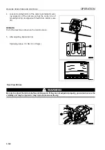
4.
Loosen mounting bolt (4) of the camera and adjust mount-
ing angle (A) of the camera so that the center line of
mounting bolt (4) is aligned with fourth-from-bottom scale
(B).
REMARK
Part of the machine is shown on the monitor screen.
5.
After adjusting, tighten bolt (4).
Tightening torque: 3-5 Nm (0.3-0.5 kgm)
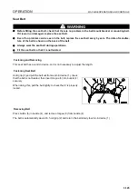
Rear View Mirrors
WARNING
Be sure to adjust the mirrors before starting work. If they are not adjusted properly, you cannot secure the
visibility and may be injured or may injure someone seriously.
Summary of Contents for PC450-8
Page 2: ......
Page 3: ...FOREWORD 11 ...
Page 66: ...SAFETY MAINTENANCE INFORMATION SAFETY 2 42 ...
Page 351: ...SPECIFICATIONS 15 ...
Page 355: ...SPECIFICATIONS SPECIFICATIONS 5 5 6 7m Boom PC450 8 ...
Page 356: ...SPECIFICATIONS SPECIFICATIONS 5 6 6 7m Boom PC450LC 8 ...
Page 357: ...SPECIFICATIONS SPECIFICATIONS 5 7 6 7m Boom PC450LCHD 8 ...
Page 359: ...SPECIFICATIONS SPECIFICATIONS 5 9 7 0m Boom PC450 8 ...
Page 360: ...SPECIFICATIONS SPECIFICATIONS 5 10 7 0m Boom PC450LC 8 ...
Page 410: ...SUPER LONG FRONT BOOM AND ARM ATTACHMENTS ANDD OPTIONS 6 50 ...
Page 436: ...OPERATION HIGH REACH DEMOLITION EQUIPMENT 27M 7 26 3 Extend arm cylinder Arm cylinder ...
Page 469: ...INDEX 18 ...
Page 470: ...INDEX 8 2 ...
Page 473: ...COLOPHON 18 ...


