SUPER LONG FRONT BOOM AND ARM
ATTACHMENTS ANDD OPTIONS
6-42
TRANSPORT & STORAGE OF SUPER LONG FRONT MACHINE
6
INSTALLATION OF SUPPORTING LINK
6
q
For transportation or storage, always use the supporting
link to secure the arm and boom as shown. This will help
to prevent excessive force bearing on the boom and arm.
q
Other precautions for transport and storage can be found
in "TRANSPORTATION PROCEDURE” 3-169. of the stan-
dard machine manual.
Procedure for installing link
1.
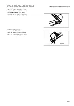
Lower the boom and extend the arm cylinder to set in the stow posture.
2.
When the arm cylinder is almost at the end of the stroke,
lower the boom slowly to bring the bucket or bucket link
into light contact with the ground.
3.
Remove the A end of the supporting link from the boom
(held by a pin), then install it to the arm with the pin. When
doing this, raise the boom slightly and retract the arm cylin-
der slightly from the end of its stroke (5 mm - 10 mm) to
align the holes correctly.
4.
It is dangerous to carry out this operation with the arm
raised from the ground.
Supporting link - weight 30 kg
Supporting link
Boom
Snap ring
Arm
Pin
Summary of Contents for PC450-8
Page 2: ......
Page 3: ...FOREWORD 11 ...
Page 66: ...SAFETY MAINTENANCE INFORMATION SAFETY 2 42 ...
Page 351: ...SPECIFICATIONS 15 ...
Page 355: ...SPECIFICATIONS SPECIFICATIONS 5 5 6 7m Boom PC450 8 ...
Page 356: ...SPECIFICATIONS SPECIFICATIONS 5 6 6 7m Boom PC450LC 8 ...
Page 357: ...SPECIFICATIONS SPECIFICATIONS 5 7 6 7m Boom PC450LCHD 8 ...
Page 359: ...SPECIFICATIONS SPECIFICATIONS 5 9 7 0m Boom PC450 8 ...
Page 360: ...SPECIFICATIONS SPECIFICATIONS 5 10 7 0m Boom PC450LC 8 ...
Page 410: ...SUPER LONG FRONT BOOM AND ARM ATTACHMENTS ANDD OPTIONS 6 50 ...
Page 436: ...OPERATION HIGH REACH DEMOLITION EQUIPMENT 27M 7 26 3 Extend arm cylinder Arm cylinder ...
Page 469: ...INDEX 18 ...
Page 470: ...INDEX 8 2 ...
Page 473: ...COLOPHON 18 ...


