HIGH REACH DEMOLITION EQUIPMENT 27M
DEMOLITION DIGGING BOOM INSTALLATION
7-39
REMOVAL OF DEMOLITION DIGGING EQUIPMENT.
7
REMARK
A Komatsu demolition digging equipment support system is avail-
able through your dealer. It is strongly recommended that this
system is used to hold the demolition digging equipment when it
is removed.
The procedure for removal of demolition digging equipment is
similar to the procedure for removal of demolition high reach
equipment.
Act in accordance with the following when removing demolition
digging equipment:
WARNING
q
Never retract the boom raise cylinders when the retractable pins are retracted and the equipment is in
contact with the ground.
q
If the boom is lowered under these conditions, it is possible that the demolition digging equipment will
disengage from the demolition first boom and fall.
q
Always make sure that the digging equipment is properly supported by supports or lifting equipment
of the correct rating, to prevent possibility of equipment falling.
Remember to switch the Equipment change over switch in the
cab to "High Reach" when the High Reach Demolition equipment
is installed.
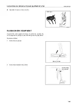
The demolition digging equipment stand comprises only one
stand section. The stand includes the items shown below:
CONNECTING DIGGING ARM TO DEMOLITION DIGGING BOOM
7
REMARK
Follow procedure FITTING DEMOLITION DIGGING EQUIPMENT. (7-35) to fit the demolition digging boom.
1.
Approach the dig arm, slowly and carefully.
2.
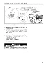
Using a crane, lift the exposed end of the dig arm so that the bore of the arm is aligned with the bore of the
boom.
3.
Insert the pin (from left to right), to make the connection between the dig boom and the arm. Apply shims to
make sure that the dig boom and the arm are a correct fit (a maximum of 0.5 mm tolerance is allowed). Shims
should be fitted to the right hand end of the pin.
4.
Lock pin in place with plate (left side of work equipment).
5.
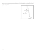
Remove the arm cylinder pin from the arm, by removing the plate and withdrawing pin.
Item
Quantity
1
Left Support
1
2
Right Support
1
3
Support Brace
2
Summary of Contents for PC450-8
Page 2: ......
Page 3: ...FOREWORD 11 ...
Page 66: ...SAFETY MAINTENANCE INFORMATION SAFETY 2 42 ...
Page 351: ...SPECIFICATIONS 15 ...
Page 355: ...SPECIFICATIONS SPECIFICATIONS 5 5 6 7m Boom PC450 8 ...
Page 356: ...SPECIFICATIONS SPECIFICATIONS 5 6 6 7m Boom PC450LC 8 ...
Page 357: ...SPECIFICATIONS SPECIFICATIONS 5 7 6 7m Boom PC450LCHD 8 ...
Page 359: ...SPECIFICATIONS SPECIFICATIONS 5 9 7 0m Boom PC450 8 ...
Page 360: ...SPECIFICATIONS SPECIFICATIONS 5 10 7 0m Boom PC450LC 8 ...
Page 410: ...SUPER LONG FRONT BOOM AND ARM ATTACHMENTS ANDD OPTIONS 6 50 ...
Page 436: ...OPERATION HIGH REACH DEMOLITION EQUIPMENT 27M 7 26 3 Extend arm cylinder Arm cylinder ...
Page 469: ...INDEX 18 ...
Page 470: ...INDEX 8 2 ...
Page 473: ...COLOPHON 18 ...

