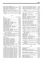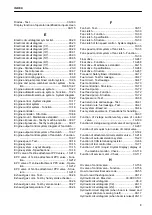
INDEX
Symbols
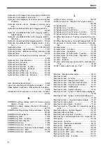
1st-line attachment PPC valve (with EPC valve).........
...................................................................10-208
1st-line attachment PPC valve (with EPC valve) -
Maintenance standard................................. 60-56
1st-line attachment PPC valve (with EPC valve) - Op-
eration........................................................10-210
1st-line attachment PPC valve (with EPC valve) -
Structure.................................................... 10-208
1st-line attachment PPC valve EPC valve - Mainte-
nance standard............................................ 60-58
2-stage suction safety valve of control valve - Opera-
tion............................................................. 10-190
2-stage suction-safety valve of control valve.... 10-189
2-stage swing relief valve of swing motor......... 10-237
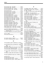
A
Abbreviation List.. 00-6,01-3,10-5,20-3,30-5,60-3,90-3
Abnormality record (Electrical Sys Abnormality Re-
cord) - Confirm...........................................30-134
Abnormality record (Mechanical Sys Abnormality Re-
cord) - Confirm...........................................30-133
Abnormality Record Menu................................ 30-133
Actions if fire occurs............................................00-24
Adjust play of work equipment and swing PPC valve..
.....................................................................30-93
Adjustment Menu.............................................. 30-154
Adjustment menu (Attachment Flow Adjustment) -
Adjust.........................................................30-157
Adjustment menu (Fan Rotation Mode Selection) -
Adjust.........................................................30-158
Adjustment menu (Low Speed) - Adjust........... 30-156
Adjustment menu (Pump Absorption Torque (F)) - Ad-
just............................................................. 30-154
Adjustment menu (Pump Absorption Torque (R)) -
Adjust.........................................................30-155
Adjustment menu (Pump calibration: Matching speed
calibration) - Adjust.................................... 30-165
Adjustment menu (Pump calibration: Matching speed
check) - Adjust........................................... 30-159
Adjustment menu (Pump calibration: Restore to De-
fault) - Adjust..............................................30-166
Alternator belt - Test............................................30-52
Arm - Dimensions............................................... 60-68
Arm cylinder - Isolate the part causing hydraulic drift..
.....................................................................30-94
Arm cylinder - Maintenance standard................. 60-73
Arm cylinder - Test oil leakage............................ 30-96
Arm hydraulic drift prevention valve of control valve....
...................................................................10-178
Arm hydraulic drift prevention valve of control valve -
Function..................................................... 10-179
Arm quick return valve of control valve............. 10-184
Arm quick return valve of control valve - Operation.....
...................................................................10-184
Arm regeneration circuit of control valve...........10-160
Arm regeneration circuit of control valve - Function.....
...................................................................10-160
Arm regeneration circuit of control valve - Operation...
...................................................................10-162
Attachment circuit selector valve...................... 10-217
Attachment circuit selector valve - Maintenance
standard.......................................................60-61
Attachment circuit selector valve - Operation... 10-218
Attachment circuit selector valve - Structure.....10-217
Attachment oil flow adjuster system..................10-202
Auto-deceleration system................................... 10-20
Auto-deceleration system - Operation................ 10-21
Auto-decelerator - System diagram.................... 10-20
Auto-tensioner - Test...........................................30-54
Automatic idle stop system................................. 10-28
Automatic idle stop system - Function................ 10-28
Automatic idle stop system - System diagram.... 10-28
Automatic tensioner - Test.................................. 30-54
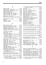
B
Batery disconnect switch.................................... 10-14
Battery disconnect switch - Function.................. 10-14
Battery disconnect switch - Handle...................30-182
Blowby gas pressure sensor...............................10-32
Blowby pressure - Test........................................30-34
Blowby pressure sensor - Function.....................10-32
Blowby pressure sensor - Structure....................10-32
Boom cylinder - Maintenance standard.............. 60-72
Boom cylinder - Test oil leakage......................... 30-96
Boom cylinder and bucket cylinder - Method for test-
ing the parts causing hydraulic drift............. 30-94
Boom hydraulic drift prevention valve of control valve.
...................................................................10-175
Boom hydraulic drift prevention valve of control valve
- Function...................................................10-175
Boom hydraulic drift prevention valve of control valve
- Operation.................................................10-176
Boom lower relief pressure (high pressure set side) -
Adjust...........................................................30-72
Boom lower relief pressure (low pressure set side) -
Adjust...........................................................30-72
Boom regeneration circuit of control valve........10-157
Boom regeneration circuit of control valve - Function..
...................................................................10-157
Boom regeneration circuit of control valve - Operation
...................................................................10-159
Boost pressure - Test.......................................... 30-21
Boost pressure - Test by testing tools................. 30-22
Boost pressure - Test on machine monitor......... 30-21
Boot-up system................................................... 10-11
Boot-up system - Layout drawing........................10-11
Bucket - Dimensions........................................... 60-70
INDEX
1
Summary of Contents for PC500LC-10R
Page 1: ...HYDRAULIC EXCAVATOR SEN06722 00 PC500LC 10R SERIAL NUMBERS 100001 and up...
Page 2: ......
Page 3: ...00 INDEX AND FOREWORD PC500LC 10R 00 1...
Page 76: ......
Page 77: ...01 SPECIFICATIONS PC500LC 10R 01 1...
Page 94: ......
Page 95: ...10 STRUCTURE AND FUNCTION PC500LC 10R 10 1...
Page 177: ...When balanced 10 STRUCTURE AND FUNCTION CLSS PC500LC 10R 10 83...
Page 178: ...When lever is returned to fine control state CLSS 10 STRUCTURE AND FUNCTION 10 84 PC500LC 10R...
Page 179: ...When lever is pulled at a stroke 10 STRUCTURE AND FUNCTION CLSS PC500LC 10R 10 85...
Page 180: ...When lever is in stroke end CLSS 10 STRUCTURE AND FUNCTION 10 86 PC500LC 10R...
Page 377: ...20 STANDARD VALUE TABLE PC500LC 10R 20 1...
Page 407: ...30 TESTING AND ADJUSTING PC500LC 10R 30 1...
Page 583: ...30 TESTING AND ADJUSTING METHOD FOR STARTING UP KOMTRAX TERMINAL PC500LC 10R 30 177...
Page 604: ......
Page 605: ...60 MAINTENANCE STANDARD PC500LC 10R 60 1...
Page 636: ...MAINTENANCE STANDARD OF MAIN PUMP 60 MAINTENANCE STANDARD 60 32 PC500LC 10R...
Page 638: ...MAINTENANCE STANDARD OF SWING MOTOR 60 MAINTENANCE STANDARD 60 34 PC500LC 10R...
Page 641: ...60 MAINTENANCE STANDARD MAINTENANCE STANDARD OF TRAVEL MOTOR PC500LC 10R 60 37...
Page 644: ...MAINTENANCE STANDARD OF CONTROL VALVE 60 MAINTENANCE STANDARD 60 40 PC500LC 10R...
Page 646: ...MAINTENANCE STANDARD OF CONTROL VALVE 60 MAINTENANCE STANDARD 60 42 PC500LC 10R...
Page 648: ...MAINTENANCE STANDARD OF CONTROL VALVE 60 MAINTENANCE STANDARD 60 44 PC500LC 10R...
Page 650: ...MAINTENANCE STANDARD OF CONTROL VALVE 60 MAINTENANCE STANDARD 60 46 PC500LC 10R...
Page 652: ...MAINTENANCE STANDARD OF CONTROL VALVE 60 MAINTENANCE STANDARD 60 48 PC500LC 10R...
Page 658: ...MAINTENANCE STANDARD OF TRAVEL PPC VALVE 60 MAINTENANCE STANDARD 60 54 PC500LC 10R...
Page 668: ...MAINTENANCE STANDARD OF WORK EQUIPMENT LINKAGE 60 MAINTENANCE STANDARD 60 64 PC500LC 10R...
Page 679: ...90 CIRCUIT DIAGRAMS PC500LC 10R 90 1...
Page 692: ......
Page 694: ......
Page 696: ......
Page 698: ......
Page 700: ......
Page 704: ...Symbol Content Buzzer Antenna SYMBOLS USED IN ELECTRICAL CIRCUIT DIAGRAM 90 26 PC500LC 10R...
Page 706: ......
Page 708: ......
Page 710: ......
Page 712: ......
Page 714: ......
Page 716: ......
Page 718: ......
Page 720: ......
Page 722: ......
Page 724: ......
Page 726: ......
Page 728: ......
Page 730: ......
Page 732: ......
Page 734: ......
Page 736: ......
Page 738: ......
Page 740: ......
Page 742: ......
Page 744: ......
Page 746: ......
Page 748: ......
Page 757: ......

