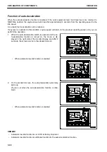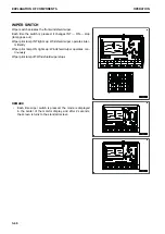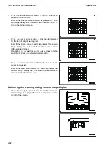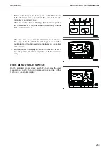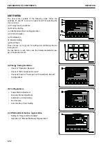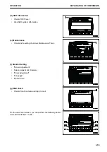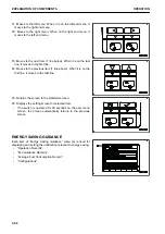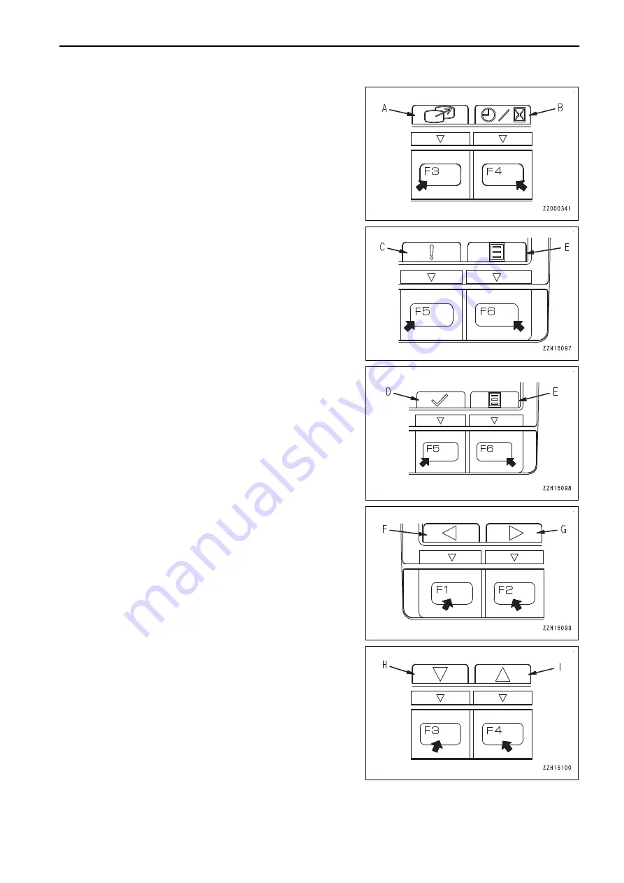
(A) Switch F3: Camera image selector switch.
(B) Switch F4: Service meter/clock display selector switch
(C) Switch F5: Current Abnormality display switch
(Only while caution lamp is lit)
(D) Switch F5: ECO guidance erase switch
(While ECO guidance is displayed)
(E) Switch F6: User menu display switch
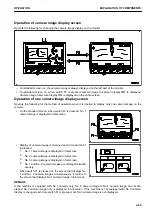
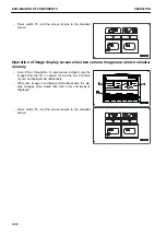
Guidance icons and their functions differ with the contents of
the displayed screen, but representative guidance icons fre-
quently used and their functions are as follows:
(F) Switch F1: Moves to the left item. (When on the left end, it
moves to the right end.)
(G) Switch F2: Moves to the right item. (When on the right end,
it moves to the left end.)
(H) Switch F3: Moves to the item below (forward). (When on
the last line, it moves to the first line on the next page.)
(I) Switch F4: Moves to the item above (backward). (When on
the first line, it moves to the last line on the previous page.)
OPERATION
EXPLANATION OF COMPONENTS
3-41
Summary of Contents for PC700LC-11
Page 2: ......
Page 23: ...LOCATION OF SAFETY LABELS 5 SAFETY SAFETY LABELS 2 3...
Page 66: ......
Page 316: ......
Page 396: ......
Page 397: ...SPECIFICATIONS 5 1...
Page 401: ...For 7 6m Boom SPECIFICATIONS SPECIFICATIONS 5 5...
Page 402: ...SPECIFICATIONS SPECIFICATIONS 5 6...
Page 426: ......
Page 427: ...REPLACEMENT PARTS 7 1...
Page 434: ......


