2.
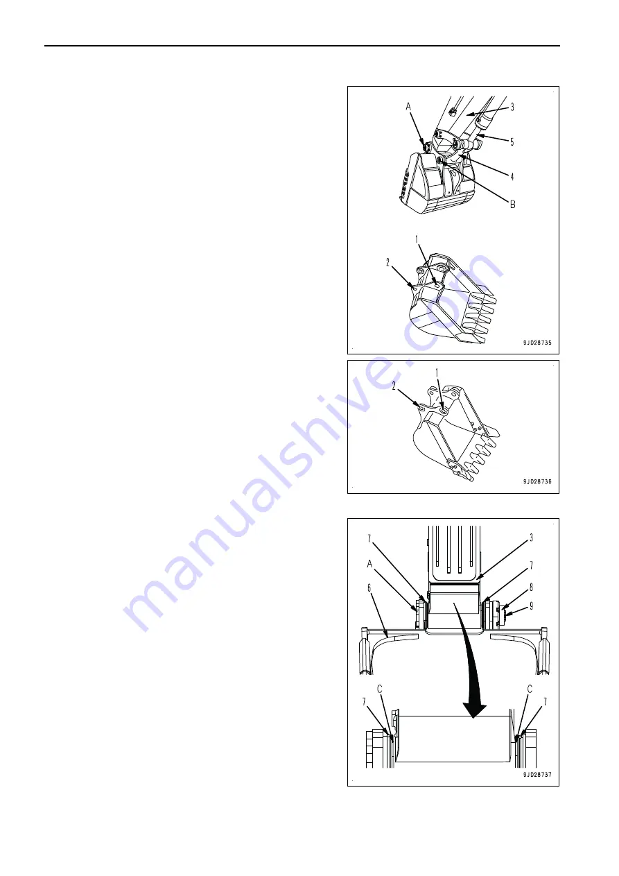
Remove the stopper at the pin end, and remove the pins
(A) and (B) to remove the bucket.
REMARK
After removing the pins, make sure that mud or sand does
not get on them.
Dust seals are fitted at both ends of the bushings, be care-
ful not to damage them.
3.
Align the pin hole of arm (3) with hole (1) of the bucket to
be replaced, then align the pin hole of link (4) with hole (2),
and install the pins (A) and (B) which are coated with
grease.
REMARK
• Perform installation in the reverse order to removal.
• Fit the O-ring (7) to the bucket (6) as shown in the fig-
ure since it is damaged easily when bucket (6) is in-
stalled. After inserting the pin, fit it in the regular
groove (C).
• Install the stopper plate (8) and bolt (9) for each pin,
then grease the pins.
• Lubricate with grease thoroughly until the grease
comes out from the end faces.
• If the dust seal is damaged when replacing the bucket,
replace it. If a damaged one is used without being re-
placed, sand and dirt may enter the part of pin and
cause abnormal wear of the pin.
MACHINE OPERATIONS AND CONTROLS
OPERATION
3-198
Summary of Contents for PC700LC-11
Page 2: ......
Page 23: ...LOCATION OF SAFETY LABELS 5 SAFETY SAFETY LABELS 2 3...
Page 66: ......
Page 316: ......
Page 396: ......
Page 397: ...SPECIFICATIONS 5 1...
Page 401: ...For 7 6m Boom SPECIFICATIONS SPECIFICATIONS 5 5...
Page 402: ...SPECIFICATIONS SPECIFICATIONS 5 6...
Page 426: ......
Page 427: ...REPLACEMENT PARTS 7 1...
Page 434: ......


