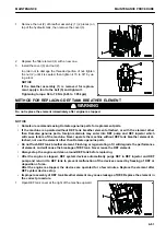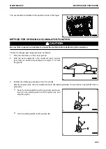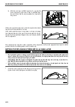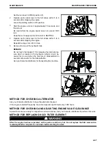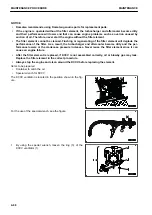
Set the lock lever to FREE position (F).
2.
Operate each control lever to the full stroke within 5 to 6
seconds after stopping the engine.
Leave the starting switch in ON position.
3.
Start the engine, and run it approximately 10 seconds, and
then stop it.
Be careful that the engine speed does not exceed 1000
rpm.
Keep the work equipment control lever in NEUTRAL.
4.
Operate each control lever to the full stroke within 5 to 6
seconds after stopping the engine.
Repeat the steps 3 to 4 for 3 times.
5.
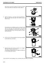
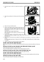
Remove the cap of the hydraulic tank.
REMARK
Do not touch the bleeder (1) for releasing the internal pres-
sure which is located in the hydraulic cylinder circuit, be-
cause this is used when the machine is disassembled in
several components for the transportation.
Ask your Komatsu distributor for transporting the machine.
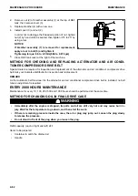
METHOD FOR CHECKING ALTERNATOR
Ask your Komatsu distributor to have the alternator checked.
If the engine is started frequently, have this inspection performed every 1000 hours.
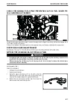
METHOD FOR CHECKING AND ADJUSTING ENGINE VALVE CLEARANCE
Special tools are necessary for inspection and maintenance. Ask your Komatsu distributor to perform this work.
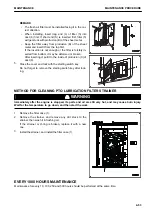
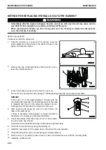
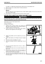
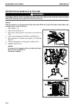
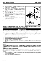
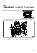
METHOD FOR REPLACING KCCV FILTER ELEMENT
k
k
WARNING
After the engine has been operated, all the parts are still very hot. Do not replace the filter element im-
mediately. Wait for all parts to cool down before starting the work.
MAINTENANCE
MAINTENANCE PROCEDURE
4-67
Summary of Contents for PC700LC-11
Page 2: ......
Page 23: ...LOCATION OF SAFETY LABELS 5 SAFETY SAFETY LABELS 2 3...
Page 66: ......
Page 316: ......
Page 396: ......
Page 397: ...SPECIFICATIONS 5 1...
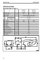
Page 401: ...For 7 6m Boom SPECIFICATIONS SPECIFICATIONS 5 5...
Page 402: ...SPECIFICATIONS SPECIFICATIONS 5 6...
Page 426: ......
Page 427: ...REPLACEMENT PARTS 7 1...
Page 434: ......

