6.
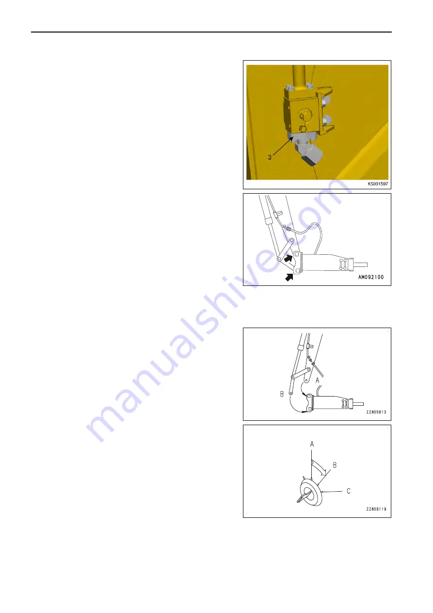
Remove the hoses on the attachment side. Fit blanking
flange assembly (3) at the stop valve bracket. Install the
plugs to the two outlets.
The plugs are used to prevent the attachment from incor-
rect operation caused by mixing in of foreign matter. After
the plugs are correctly installed, store the attachment.
7.
Pull out the mounting pins (2 places), remove the attach-
ment, then install the bucket.
For the installation procedure of the bucket, see "METHOD
FOR CHANGING BUCKET".
8.
After installing the bucket, check the oil level in hydraulic
tank.
For details, see "METHOD FOR CHECKING OIL LEVEL
IN HYDRAULIC TANK, ADDING OIL".
METHOD FOR INSTALLING ATTACHMENT
1.
Remove the bucket.
For the removal procedure of the bucket, see "METHOD FOR CHANGING BUCKET".
2.
Place the attachment on a horizontal place, install pin (A)
and then pin (B) in this order to the arm.
Pin (A) 115 mm diameter
Pin (B) 115 mm diameter
3.
Lower the attachment to the ground and stop the engine.
4.
Turn the starting switch to ON (B) position.
HANDLE MACHINE READY FOR INSTALLATION OF ATTACHMENT
ATTACHMENTS AND OPTIONS
6-10
Summary of Contents for PC700LC-11
Page 2: ......
Page 23: ...LOCATION OF SAFETY LABELS 5 SAFETY SAFETY LABELS 2 3...
Page 66: ......
Page 316: ......
Page 396: ......
Page 397: ...SPECIFICATIONS 5 1...
Page 401: ...For 7 6m Boom SPECIFICATIONS SPECIFICATIONS 5 5...
Page 402: ...SPECIFICATIONS SPECIFICATIONS 5 6...
Page 426: ......
Page 427: ...REPLACEMENT PARTS 7 1...
Page 434: ......

