2.
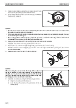
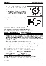
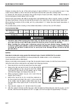
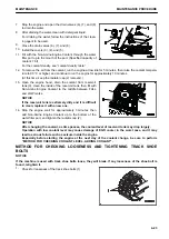
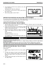
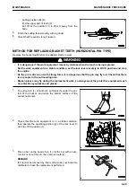
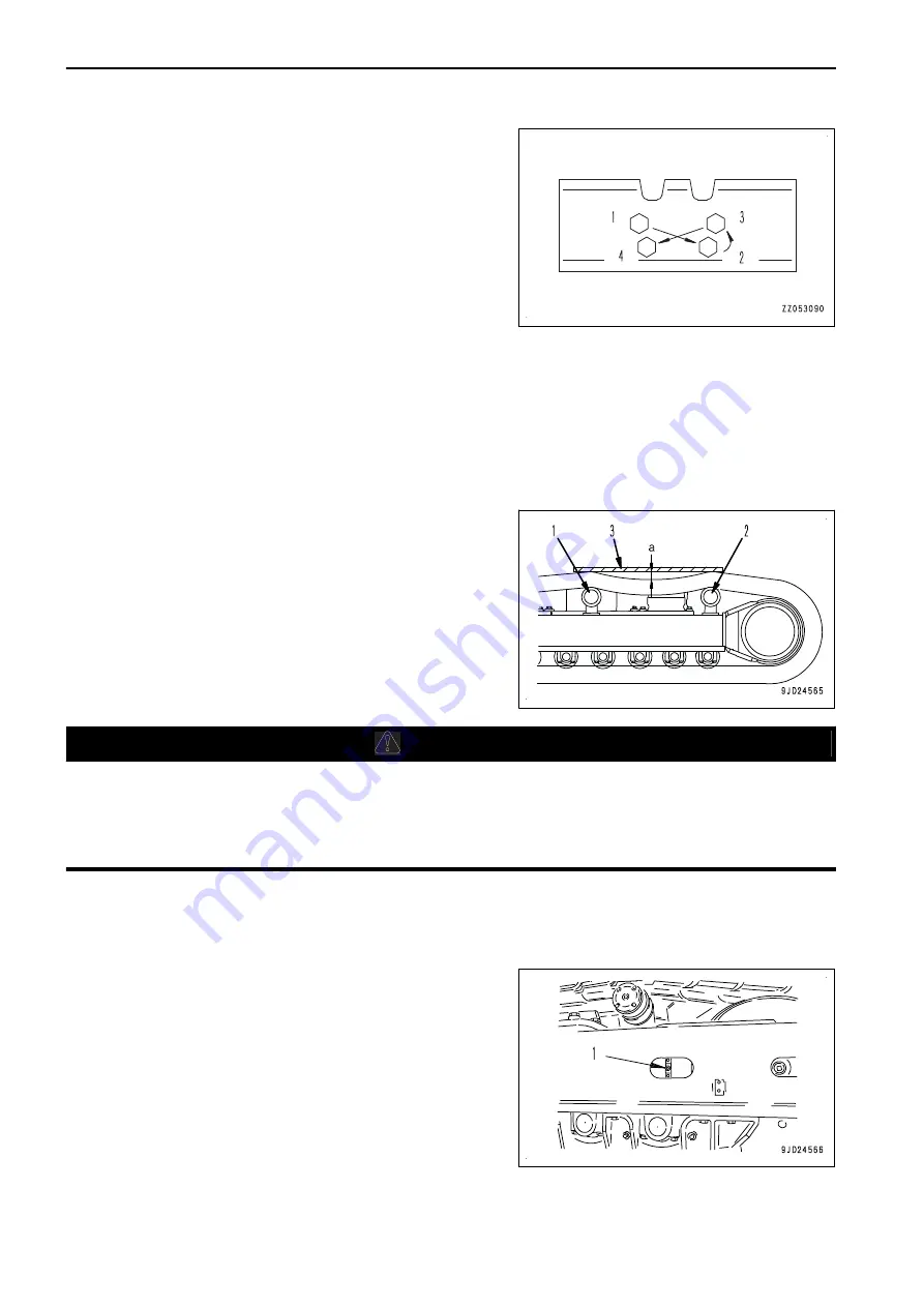
If any looseness of the bolt is found, tighten it in the order
shown in the figure.
Tightening torque: 784±78 Nm {80±8 kgm}
3.
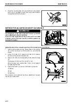
Check that the nut and shoe are in close contact with the
link contact surface.
4.
After checking, tighten a further 120±10 °.
METHOD FOR CHECKING AND ADJUSTING TRACK TENSION
The wearing of the pins and bushings in the undercarriage depends on the working condition and type of soil.
Check the track tension occasionally and keep it in the standard range.
Perform check and adjustment on a level and firm ground.
METHOD FOR CHECKING TRACK TENSION
1.
Run the engine at low idle, then move the machine forward for a distance equal to the track length on
ground, and slowly stop the machine.
2.
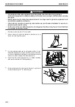
Prepare the straight wooden bar (3) which has an enough
length from the second carrier roller (1) to the third carrier
roller (2). Put it onto the track shoe.
3.
Measure the maximum deflection (a) between the bottom
surface of the wooden bar and top surface of the track
shoes.
Standard deflection
Deflection (a) should be 10 to 30 mm .
If the deflection is out of the standard range, adjust it into
the standard range.
k
k
WARNING
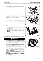
Never loosen the plug (1) more than 1 turn.
If plug (1) is loosened more than 1 turn, there is a danger of plug (1) flying out under the high internal
pressure of the grease.
Never loosen any part other than plug (1). Never put your face in the mounting direction of plug (1).
If the track tension cannot be loosened by the above procedure, ask your Komatsu distributor for repair.
METHOD FOR INCREASING TRACK TENSION
Items to be prepared
Grease pump
1.
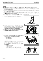
Pump in grease through the valve (1) by using a grease
gun.
2.
To check if the tension is correct, run the engine at low
idle, move the machine slowly forward (by an amount
equal to the length of track on the ground), then stop the
machine.
3.
Check the track tension again, and if the tension is not cor-
rect, adjust it again.
MAINTENANCE PROCEDURE
MAINTENANCE
4-24
Summary of Contents for PC700LC-11
Page 2: ......
Page 23: ...LOCATION OF SAFETY LABELS 5 SAFETY SAFETY LABELS 2 3...
Page 66: ......
Page 316: ......
Page 396: ......
Page 397: ...SPECIFICATIONS 5 1...
Page 401: ...For 7 6m Boom SPECIFICATIONS SPECIFICATIONS 5 5...
Page 402: ...SPECIFICATIONS SPECIFICATIONS 5 6...
Page 426: ......
Page 427: ...REPLACEMENT PARTS 7 1...
Page 434: ......

