3.
After removing blanking flange assembly (3), replace o-
ring and connect the attachment hose (4) provided by the
attachment manufacturer.
REMARK
Method of connection varies depending on the attachment
manufacturer because size of the fitting, added accumula-
tor, etc. are different. Consult your Komatsu distributor.
PEDAL OPERATION AND OIL FLOW OF MACHINE EQUIPPED WITH ATTACH-
MENT
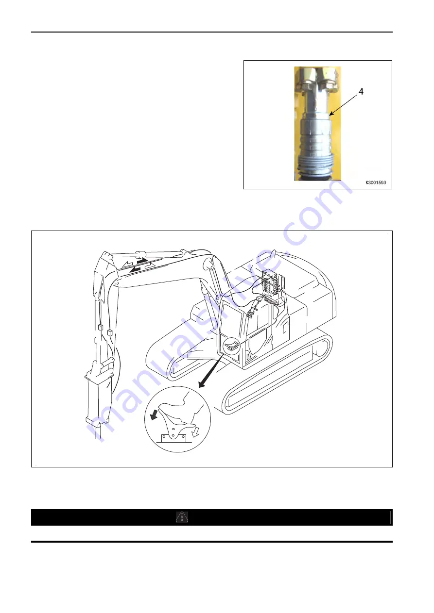
The direction of operation of the pedal and the path of the oil flow is as shown in the diagram below.
KS000404
• When the front pedal is depressed, oil flows to the piping on the left side of the work equipment.
• With the pedal in the neutral position, or the rear pedal depressed, oil does not flow.
METHOD FOR REMOVING AND INSTALLING ATTACHMENT
k
k
WARNING
Lower the attachment to the ground and stop the engine.
HANDLE MACHINE READY FOR INSTALLATION OF ATTACHMENT
ATTACHMENTS AND OPTIONS
6-8
Summary of Contents for PC700LC-11
Page 2: ......
Page 23: ...LOCATION OF SAFETY LABELS 5 SAFETY SAFETY LABELS 2 3...
Page 66: ......
Page 316: ......
Page 396: ......
Page 397: ...SPECIFICATIONS 5 1...
Page 401: ...For 7 6m Boom SPECIFICATIONS SPECIFICATIONS 5 5...
Page 402: ...SPECIFICATIONS SPECIFICATIONS 5 6...
Page 426: ......
Page 427: ...REPLACEMENT PARTS 7 1...
Page 434: ......


